


vii
• Do not operate your equipment with any cover(s) removed.
• The internal components, including memory modules, can become extremely hot during operation.
Allow sufficient time to cool before handling.
• Do not use damaged equipment, including exposed, frayed, or damaged power cords.
• When connecting or disconnecting power to hot-pluggable power supplies:
– Install the power supply before connecting the power cable to the power supply.
– Unplug the power cable before removing the power supply.
– Disconnect all sources of power from the system by unplugging all power cables from the power
supplies.
• Do not use the equipment where it can get wet. Protect equipment from liquid intrusion. If your
equipment gets wet, disconnect power to the equipment and to any attached devices. If the computer
is connected to an electrical outlet, turn off the AC power at the circuit breaker before attempting to
remove the power cables from the electrical outlet. Disconnect any attached devices.
• Do not push any objects into the air vents or openings of the equipment. Doing so can cause fire or
electric shock.
• To prevent risk of exposure to laser, do not disable or open any Optical Disk Drives (ODD), such as a
CD-ROM, CDR/W, DVD drive assembly.
CAUTION:
Observe the following instructions to help prevent damage to hardware or loss of data:
• Do not attempt to service the equipment yourself, except as explained in your documentation or in
instructions otherwise provided to you by Dell. Always follow installation and service instructions
closely.
• If your hardware has a voltage selection switch on the power supply, be sure to set it for the voltage that
most closely matches the AC power available at your location.
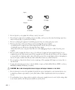
Input
Output
DC Input
AC Input
DC Output
AC Output
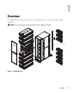
Содержание DSS 9000
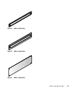
Страница 43: ...Bus bar overview 32 Figure 40 Bus bar bottom P positive red Figure 41 Bus bar bottom N negative black ...
Страница 65: ...Installing and removing system components 54 Figure 64 Removing the fan module ...
Страница 72: ...61 Installing and removing system components Figure 72 Securing a cable with a cable clip ...
Страница 79: ...Installing and removing system components 68 Figure 80 Installing the BC ...


