


Power bay overview
19
4
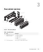
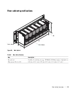
Power bay overview
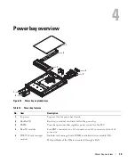
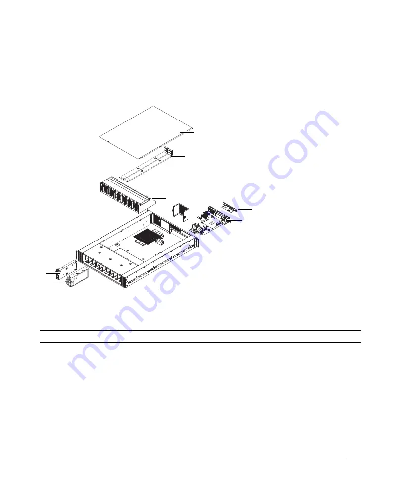
Figure 25. Power bay exploded view
Table 14. Power bay features
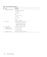
No.
Item
Description
1
Top cover
Top cover for the power bay chassis.
2
Bus Bar PB
Bar strip to conduct electricity within the power bay.
3
PBPM
Power bay power module regulates power control for the PSU.
4
Rear IO module
Four RJ45 connectors, one 1x5 connector, one 1x6 connector and one 2x8
connector.
5
DSS 9000 rack manager
module
Includes rack manager board (RMB) and infrastructure module (IM).
MC and blocks of the IM are networked through a LAN.
1
2
3
4
6
5
7
Содержание DSS 9000
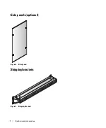
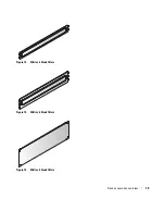
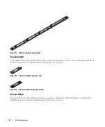
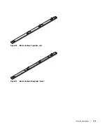
Страница 43: ...Bus bar overview 32 Figure 40 Bus bar bottom P positive red Figure 41 Bus bar bottom N negative black ...
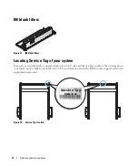
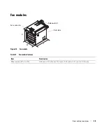
Страница 65: ...Installing and removing system components 54 Figure 64 Removing the fan module ...
Страница 72: ...61 Installing and removing system components Figure 72 Securing a cable with a cable clip ...
Страница 79: ...Installing and removing system components 68 Figure 80 Installing the BC ...


