Installation
6. For AUI cable locate the adapters AUI connector and move the slide latch to the open
position. Connect the AUI cable to the AUI connector on the adapter then move the
slide latch to the closed position to lock the cable in place
STK3494 Model
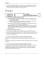
1. Connect the communication cable as follows:
a. Turn off the power to the 3494 unit and to the modem and unplug the power
cables from the outlets.
b. Connect the supplied communication cable between the 3494 Rear Panel LINE
connector and the appropriate connector on your modem.
c. Reconnect your modem and 3494 unit power cables to properly grounded power
source outlets. Turn the modem and controller ON.
NOTE:
Pre-terminated modem cable is supplied as part of your order. The DB-25
to DB-25 cables are supplied for RS-232 communication option. If you specified
other communication options in your order (V.35 or X.21), the appropriate modem
cable is provided.
2. Connect the Twinax cable as follows:
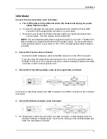
Connect the 4289 multiplexer cable to the DB9 connector on the TWX connector.
If you are using the external Twinax expansion unit, connect the expansion cable to the EXP
connector on the controller rear panel, and the multiplexer cable to the DB9 connector
on the Twinax expansion unit.
3. Connect the Token-Ring adapter cable (where applicable) as follows:
To install the Token-Ring adapter card refer to Adapter Installation Procedure (section
2.2.2).
Connect the Token-Ring cable to the DB9 connector on the TRN connector on the controller
front panel.
4. Connect the Ethernet adapter cable (where applicable) as follows:
To install the Ethernet adapter card refer to Adapter Installation Procedure (section 2.2.2).
For Twisted pair cable make sure that your cable connector is appropriately wired for
standard 10 Base-T adapter cards. Insert the RJ-45 plug on the end of the twisted pair
cable in the connector on the front panel.
4
Содержание 3000 Series
Страница 1: ...Series 3000 STK3494 3494 User s Manual ...
Страница 2: ......

