- 23 - 115.6031.0
3
START-UP AND OPERATION
Prior to performing any work on the Vaporizer installation, the entire Start-up and Operation Section should be read
and understood.
It is critical that the materials of construction throughout the entire system from chemical source to point of usage
(i.e., piping, unions, valves, switches, rupture discs, etc.) are compatible with the chemical being used. After
completely assembling the Vaporizer system, check that the downstream equipment is ready to receive the gas
from the Vaporizer.
NOTE
It is recommended that De Nora Water Technologies be contacted to obtain the services of trained
personnel to assist and instruct plant operating personnel at the time of initial start-up. At that time the
De Nora Water Technologies service personnel will instruct plant operators in the steps to be taken
for replenishing the supply of liquid chemical when the in-service supply is exhausted. This procedure
cannot be presented in this Bulletin, since the procedure requires first hand knowledge
of the nature and complexity of the particular Vaporizer System in question.
3.1
Checking Out the Gas Dispenser(s)
1)
Check out each Gas Dispenser as described in the applicable Instruction Bulletin(s) covering
the equipment in question, allowing each automatically controlled type Dispenser to remain
on manual control following the completion of the check out procedure.
Checking each gas dispenser to verify satisfactory performance and setting each dispenser on
manual control to provide unrestricted feed rate adjustment are necessary to ensure that the
Dispenser(s) operates as required and directed in the subsequent steps of this procedure.
2)
Use dry air (-40°F Dew point) instead of Chlorine, Sulfur Dioxide, or Ammonia gas to verify that
the gas dispenser is operating properly. Refer to the Gas Dispenser(s) Instruction Bulletin for
the proper method.
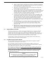
CAUTION
Chlorine or Sulfur Dioxide will combine with water (even the moisture in air)
to form a very corrosive acid. When any piping section is opened or disconnected for servicing,
the opening must be sealed immediately. This also applies when changing chemical containers.
3.2 Filling the Water Chamber
WARNING
Potable water is the only acceptable heat transfer medium. No other fluid is to be used.
NOTE
Should the water supply contain particulate matter, a "Y" strainer piped
prior to the solenoid valve is required. (P/N BM-5101)
1) Open all shut-off valves in the water supply line to the water supply piping assembly.
Then close the drain valve and open the throttling valve of this assembly.
2) Fill the water chamber to operating level, as evidenced by water being discharged to drain
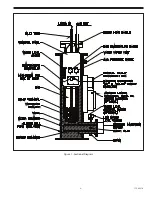
through the open drain connection in the rear of the Vaporizer (refer to Figure 3). Observe
the sight glass to check the water level.
3) When the chamber is filled to operating level, gradually close the throttling valve to
establish a small but constant by-pass flow of water to drain (if the system is supplied with
a manual valve only).
If the water supply piping assembly includes a solenoid valve (to reduce the water supply
requirements to an absolute minimum) or a flowmeter (to provide visual indication of the
by-pass flow rate), take the necessary steps to fill the water chamber to operating level and
establish the proper operation of the particular system on site.
Содержание Capital Controls 71V3B Series
Страница 1: ... 1 115 6031 0 Instruction Manual Series 71V3B Electrically Heated Vaporizer CAPITAL CONTROLS ...
Страница 9: ... 9 115 6031 0 Figure 1 Sectional Diagram ...
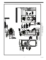
Страница 17: ... 17 115 6031 0 Figure 4 Outline Mounting Dimensions 12 kW 15 kW Heaters ...
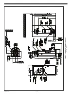
Страница 18: ...115 6031 0 18 Figure 5 Outline Mounting Dimensions 18 kW Heater ...
Страница 42: ...115 6031 0 42 PAGE INTENTIALLY LEFT BLANK ...

