115.6031.0
- 12 -
1.3.2.9 Low Water Level Switch
A low water level switch is furnished to sense the level of the water in the water chamber. This
pressure operated switch, which provides a contact closure on falling water level, serves to actuate
a remote visual and/or audible alarm device (supplied by the user) in the event that the water level
in the chamber falls below the minimum Operating level. This ensures that the occurrence of an
abnormally low water level condition will be brought to the immediate attention of operating
personnel. Also, the switch contains a second set of contacts used to de-energize the heater
contactor coil should the water level fall below the minimum operating water level.
1.3.2.10 Gas Temperature and Pressure Gauges
The gas temperature and pressure gauges, having their sensing elements constructed of materials
capable of withstanding the corrosive action of the gas in question, provide visual indication of the
temperature and pressure of the gas in the vaporizing chamber. The readings on these gauges
provide the means for determining the number of degrees superheat being added to the gas prior
to discharge from the chamber. This information is essential for determining that the Vaporizer
is performing properly.
1.3.2.11 Control Circuit Connection Box
The control circuit connection box houses the terminal strip which provides the terminal
interconnections between the internal control circuits and all local and/or remote control and/or
alarm
devices.
1.3.2.12 Cabinet
A high impact polystyrene plastic cabinet, containing a panel cutout, encloses and protects the
panel mounted gauges and controls.
1.3.3 Auxiliary Components
1.3.3.1 Pressure Relief Valve
The ASME Boiler and Pressure Vessel Code
requires a pressure relief valve on each Vaporizer.
This component is mandatory on all systems
, and is available from De Nora Water Technologies.
The pressure relief valve serves to automatically relieve excess gas pressure which would otherwise
develop in the event that the Vaporizer is isolated by valve closure. The pressure relief valve is set at
300 psig and its outlet must be vented to a safe area.
WARNING
Do not install a valve between the gas discharge of the Vaporizer and the pressure relief valve.
1.3.3.2 Electrically Operated Pressure Reducing and Shut-Off Valve
The optional electrically operated pressure reducing and shut-off valve, operating from the water
low temperature and low water level switches, serves two important functions.
•
To automatically shut off all flow from the Vaporizer in the event that the water temperature falls
below the minimum desirable operating temperature or the water level falls below a preset low
level. This prevents the possibility of liquid chemical from entering and flooding the gas handling
components. The valve also closes if a power failure occurs.
•
To lower the pressure of the gas being directed to the using system. This reduces the possibility of
liquefaction (gas vapors condensing to form liquid chemical) from occurring within any portion
of the gas discharge header on the downstream side of this valve.
The electrically operated pressure reducing and shut-off valve is factory set to 40 psig for
Chlorine and Ammonia service, and 15 psig for Sulfur Dioxide service.
This component is a recommended option, and is available from De Nora Water Technologies.
Содержание Capital Controls 71V3B Series
Страница 1: ... 1 115 6031 0 Instruction Manual Series 71V3B Electrically Heated Vaporizer CAPITAL CONTROLS ...
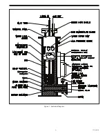
Страница 9: ... 9 115 6031 0 Figure 1 Sectional Diagram ...
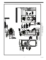
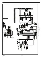
Страница 17: ... 17 115 6031 0 Figure 4 Outline Mounting Dimensions 12 kW 15 kW Heaters ...
Страница 18: ...115 6031 0 18 Figure 5 Outline Mounting Dimensions 18 kW Heater ...
Страница 42: ...115 6031 0 42 PAGE INTENTIALLY LEFT BLANK ...


