- 15 - 115.6031.0
Heat tracing of the pipe section between the Vaporizer and pressure reducing valve may also be advisable to
maintain the gas superheat temperature. This is especially true for Sulfur Dioxide service. Refer to the super heat
curves further in this manual. Note also that the addition of a gas filter in this pipe section will act as a heat sink
further reducing the super heat temperature.
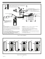
As illustrated in Figure 2, the emergency and servicing vent line must be connected to the gas discharge line using
a “Tee” coupling. This connection should be made at some point between the Vaporizer outlet and the first
shut-off valve in this line. This vent line, as well as the diaphragm rupture vent line, must be extended to a suitable
area (outside the building for indoor installations) where gas fumes cannot cause damage or endanger operating
personnel. These lines must be arranged to prevent low spots where condensed water vapor could be trapped.
Their ends must be turned downward to keep out water and a fine mesh plastic screen installed over their outlets to
prevent the entrance of insects.
2.1
Electrical Interconnections
Control circuit protection (provided by user) shall not exceed 15 amperes.
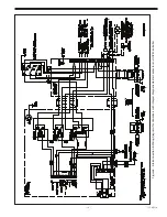
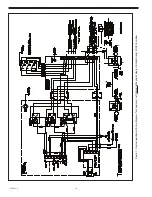
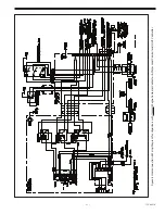
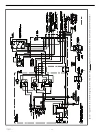
Information pertaining to the wiring interconnections that must be made to the terminal strip in the
control circuit connection box is provided on the Wiring Diagram(s) furnished with these instructions.
The Wiring Diagrams shown in Figures 6 through 9 provide typical versions of the function and
operation of the various control and/or alarm circuits.
2.2 Heater Connections
In accordance with the National Electrical Code (NEC), NFPA 70, Article 424-70, Resistance-type Boilers, branch circuit
wiring to the heater contactor shall be rated at 125% of the rated heater current. Branch circuit protection may be
the next higher current rating over the actual heater current, not to exceed 60 amperes. The equipment ground
conductor run and the service conductors must be in accordance with Table 250-95 of the National Electrical Code.
Refer to the Wiring Diagram(s) furnished with the equipment and to Figures 6 through 13.
WARNING
Electrical Shock Hazard. AC powered electrical equipment presents a potential shock hazard.
Installation and servicing should only be performed by qualified personnel.
Содержание Capital Controls 71V3B Series
Страница 1: ... 1 115 6031 0 Instruction Manual Series 71V3B Electrically Heated Vaporizer CAPITAL CONTROLS ...
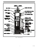
Страница 9: ... 9 115 6031 0 Figure 1 Sectional Diagram ...
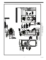
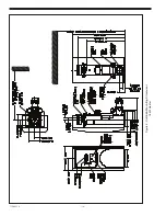
Страница 17: ... 17 115 6031 0 Figure 4 Outline Mounting Dimensions 12 kW 15 kW Heaters ...
Страница 18: ...115 6031 0 18 Figure 5 Outline Mounting Dimensions 18 kW Heater ...
Страница 42: ...115 6031 0 42 PAGE INTENTIALLY LEFT BLANK ...


