115.6031.0
- 26 -
The controller has three menus (Operation, Regulation and Initial Setting). Normal operation will be in the
Instruction Menu.
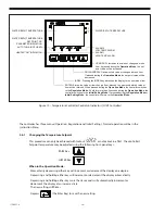
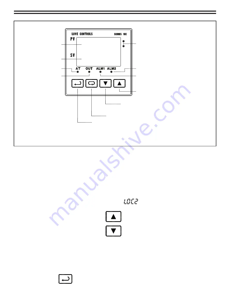
Figure 10 - Temperature Controller Controls & Indicators (LOVE Controller)
3.6.1 Changing the Temperature Setpoint
This procedure can only be achieved with lockout or no lockout in effect. The controller's
Setpoint temperature may be adjusted using the following front-panel keys:
RAISE
Key
LOWER
Key
When in the Operation Mode:
- Momentarily depressing either key will increment or decrement the display one degree.
- Depressing and holding either key will increment or decrement the display automatically.
- Depressing and holding either key more than 2 seconds will automatically increment or
decrement the display at an increased rate.
- The new setting will flicker.
- Depress (the Enter Key) to save the new setting.
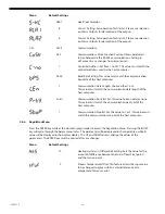
WATER BATH TEMPERATURE
HEATER "ON" INDICATION
ALARM 1
HIGH TEMP ALARM
AUTO TUNE (NOT USED)
INDEX: Pressing the INDEX key advances the display to the next menu item.
WATER BATH TEMPERATURE
ALARM 2
LOW TEMP ALARM
DOWN ARROW: Decrements a value or changes a menu item.
If pressed during the
Operation Mode
, the set point value will be
decreased.
UP ARROW: Increments a value or changes a menu
item. If pressed during the
Operation Mode
, the set
point value will be increased.
ENTER: Stores the value or item change. If not pressed, the previously stored value or
item will be retained. When pressed during the
Operation Mode
, the controller switches
to the
Regulation Mode
. If held for more than 3 seconds during the
Operation Mode
, the
controller switches to the
Initial Setting Mode
. If pressed during the
Regulation Mode
or
Initial Setting Mode
, the controller will return to the
Operation Mode
.
WATER BATH TEMPERATURE
SET POINT OR
PARAMETER INDICATION
Содержание Capital Controls 71V3B Series
Страница 1: ... 1 115 6031 0 Instruction Manual Series 71V3B Electrically Heated Vaporizer CAPITAL CONTROLS ...
Страница 9: ... 9 115 6031 0 Figure 1 Sectional Diagram ...
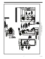
Страница 17: ... 17 115 6031 0 Figure 4 Outline Mounting Dimensions 12 kW 15 kW Heaters ...
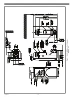
Страница 18: ...115 6031 0 18 Figure 5 Outline Mounting Dimensions 18 kW Heater ...
Страница 42: ...115 6031 0 42 PAGE INTENTIALLY LEFT BLANK ...

