115.6031.0
- 36 -
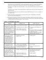
TABLE 4-1 TROUBLESHOOTING CHART
PROBLEM
PROBABLE CAUSE
CORRECTIVE ACTION
Unable to maintain evaporator
capacity.
1. Vaporizer chamber fouled, dirty or
filled with deposits, reducing
chamber capacity.
2. Tank car padding pressure high
1. Disassemble the evaporator and
clean as necessary.
2. Decrease padding pressure to
recommended levels. Increase heat
setting on temperature controller
within recommended settings.
Frost or sweating visible on the
pressure reducing valve (PRV)
and/or the adjacent piping.
1. Superheat temperature setting not
properly set for the maximum
feeder feed rate.
2. With proper superheat setting at
maximum feed rate, the chamber
capacity has been compromised
by collected impurities.
3. The PRV is mounted too far away
from the Vaporizer and the super
heat value is being lost allowing
liquefaction of the gas.
1. Refer to section 3.7 - Placing In
Operation and readjust temperature
setting accordingly.
2.Shut down the Vaporizer as described
under Section 3.10, disassemble the
vaporizer and clean as necessary.
3.Insulate the piping between the
Vaporizer and PRV. Heat trace the
piping between the Vaporizer and the
PRV. Move the PRV closer to the
Vaporizer slopping the piping towards
the Vaporizer.
When the vaporization
chamber was pulled for the
routine service, it was noted
to have corrosion and the
cathodic protection anodes
did not show signs of being
consumed. The cathodic
protection green light was on
during vaporizer operation.
1. Either the anode wiring or the
anodes had a direct path to
electrical ground.
1. When replacing the serviced
chamber in the water bath, be sure
that the insulating grommets are in
place and that the anode wiring is
correct. Exercise care when
replacing the chamber back into the
water jacket to avoid dislodging the
anodes from their bracket. After the
vaporizer chamber is returned to the
dry water bath chamber, power the
controls without heater power applied.
If the green light is on check the
cathodic protection circuitry for
connection to ground.
Содержание Capital Controls 71V3B Series
Страница 1: ... 1 115 6031 0 Instruction Manual Series 71V3B Electrically Heated Vaporizer CAPITAL CONTROLS ...
Страница 9: ... 9 115 6031 0 Figure 1 Sectional Diagram ...
Страница 17: ... 17 115 6031 0 Figure 4 Outline Mounting Dimensions 12 kW 15 kW Heaters ...
Страница 18: ...115 6031 0 18 Figure 5 Outline Mounting Dimensions 18 kW Heater ...
Страница 42: ...115 6031 0 42 PAGE INTENTIALLY LEFT BLANK ...

