Introduction
®
DriveRack™ User Manual
vi
Section i
DriveRack
™
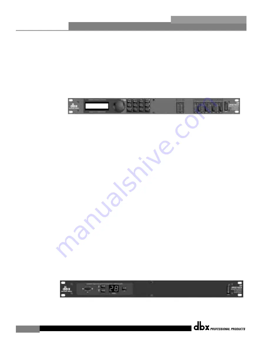
Front Panel Navigation of the 240 DriveRack
• Once all of the connections have been made and the unit is powered
up you can navigate through the entire signal path of the 240
DriveRack from the front panel of the unit. The display provides
you with a clear and concise overview of each aspect of the signal
path from the input to the output section.
The features of the front panel of the 240 DriveRack are as follows from left to right. LCD
Display
- all operational information of the DriveRack is displayed here. The display will also
notify the user if any internal clipping is taking place within the unit. The following messages
will appear:
CLIP: Pre Xover
(clipping prior to the crossover section),
CLIP: Post Xover
(clip-
ping past the crossover section), and
CLIP: Pre/Post
(clipping in both sections).
Data Wheel
- The data wheel is used to scroll through the program menu of the 240
DriveRack™. The Data Wheel is also used to perform editing functions to effects and utility
menu features.
Button Array
- Operational editing is done using this 12 button array. A com-
plete description of each button’s functionality is listed on the following page.
Input meters
-
These two 6-segment LED meters monitor the input level of the 240 DriveRack directly after the
input mixer.
Output meters
- These four 6-segment meters monitor the output levels of the
240 DriveRack directly after the output gain stage.
Mute buttons
- These four mute buttons are
used to instantly mute the output signal of the selected channel.
Front Panel Navigation of the 241 DriveRack
• Once all of the rear panel connections have been made, you can make your front or rear
panel connections from the 241 to a PC. Due to its limited design, most operations per-
formed on the unit must be done through the use of the included DriveWare™ GUI. The
front panel controls of the 241 allow you to scroll through the program menu and load the
selected program. Clip note: In the event that there is internal clipping within the signal path
of the 241, “CL” (indicating clipping) will briefly appear in the 7-segment display.
Содержание DriveRack 240
Страница 1: ...User Manual CompleteEqualization LoudspeakerManagementSystem 240 241...
Страница 5: ...INTRO CUSTOMER SERVICE INFO Defining the DriveRack WARRANTY INFO INTRODUCTION DriveRack...
Страница 11: ...Getting Started Section 1 DriveRack...
Страница 15: ...EDITING FUNCTIONS Editing Functions Section 2 DriveRack...
Страница 21: ...CONFIGURATION FUNCTIONS SOFTWARE Section 3 DriveRack...
Страница 29: ...DETAILED PARAMETERS PARAMETERS Section 4 DriveRack...
Страница 39: ...UTILITIES SECTION Utilities Section 6 DriveRack...
Страница 47: ...DriveWare GUI Section 6 DriveRack...
Страница 51: ...APPLICATION GUIDE Section 7 DriveRack...
Страница 59: ...Appendix DriveRack...
Страница 68: ...DriveRack User Manual 58 Appendix A DriveRack USER NOTES...


