background image

5.

FUSE REPLACEMENT

Should you suspect a blown fuse proceed as follows. 

WARNING 

Installation, operation and maintenance of this instrument must be performed by qualified personnel 
only.  The National Electrical Code defines a qualified person as “one who has the skills and knowledge 
related to the construction and operation of the electrical equipment and installations, and who has 
received safety training on the hazards involved.” 

a) Disconnect all power sources and cables connected to the instrument before servicing the instrument.

b) On the rear panel remove the (2) clamp slide retaining screws and remove the clamp slides from both sides of the

instrument. Next remove the (4) corner screws that retain the rear panel to gain access to the instrument.

c) Open the rear panel and replace the fuse(s) as required , replace only with same type T Slow Blow, 1A, 250V

(Littelfuse 218001.HXP, 1 A). The fuseholder wire conductors are appropriately labeled “L” for Line and “N” for

Neutral on both halves of each of the fuseholder wires. When reassembling the fuseholder(s) make sure “L” and

“L” are connected together and “N” and “N” labeled wires are connected together properly.

d) Mate the rear panel to the enclosure and replace the clamp slides back in position and secure the clamp slides

with the (2) screws previously removed from the instrument.  Next, replace the (4) corner screws to secure the

rear panel and ensure that all screws have been adequaetely tightened.

e) Power ON the instrument with the appropriate power cord and verify the instrument is functioning properly

before reconnecting the instrument to your installation.

WARNING 

For continued protection against risk of fire or shock replace only with the same type and rating 

of fuse. 

ADVERTENCIA 

Para la protección continua contra el peligro de incendio o descarga, cambie sólo por fusibles 

del mismo tipo y capacidad nominal. 

AVERTISSEMENT 

Pour assurer une protection continue contre les risques d’incendie ou de choc, ne remplacez que 

par un fusible du même type et de la même valeur nominale. 

WARNUNG 

Zum anhaltenden Schutz gegen Brand oder einen elektrischen Schlag nur gegen eine Sicherung 

desselben Typs und mit demselben Nennwert austauschen.


Page


18

Model 37

60


DC VOLT & 4-20mA PANEL METER


Содержание 3700 Series

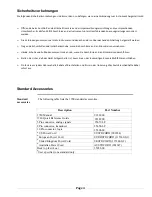
Страница 1: ...MODEL 3760 DC VOLTAGE CONDITIONER SB 1 1 INSTRUCTION MANUAL 3700 Instrument Series...

Страница 2: ...nto de este instrumento debe ser realizada por personal calificado solamente El C digo El ctrico Nacional define a una persona calificada como una que est familiarizada con la construcci n y operaci n...

Страница 3: ...lektrische Sicherheitsauflagen f r Angestellt Arbeitspl tze ANSI NFPA 70E 2012 der Vereinigten Staaten und alle zus tzlichen Arbeitsplatzsicherheitsauflagen folgen die auf Ihre Installation anwendbar...

Страница 4: ...ue el material aislante no tenga rajaduras Reemplace de inmediato cualquier parte defectuosa Mesures de S curit Les mesures de s curit suivantes doivent tre prises chaque fois qu un type de connexion...

Страница 5: ...sein wenn Sie Anschl sse an den Stromkreisen durchf hren Stellen Sie sicher da das Ger t AUSgeschaltet ist bevor Sie an der r ckw rtigen Konsole Me f hler anschlie en Pr fen Sie vor jedem Gebrauch al...

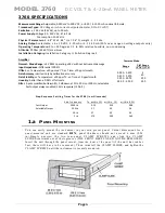
Страница 6: ...it scaling up to 199950 independent of the analog full scale signal The Model 3760 can be calibrated by the two point dead weight process involving known zero and full scale input parameters A conveni...

Страница 7: ...0 in milliseconds 3db Frequency To within 1 within 1 within 02 Fast Output 5000 Hz 0 14 0 10 0 08 Selectable Output 200 Hz 3 7 5 0 5 6 20 Hz 37 50 56 2 Hz 370 500 560 1 a PANEL MOUNTING You can easily...

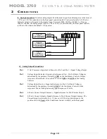
Страница 8: ...ARE J1 5 TARE ENABLE J1 6 LOGIC COM J1 7 R CAL J1 8 N C J1 9 CM FAULT J1 10 N C No connection No connection Input Analog Hold command Input Analog TARE command External TARE enable input Logic Common...

Страница 9: ...n external switch PLC or relay The LOG COM signal is used to activate the analog HOLD or Analog TARE offset to the meter s display and analog output signals present on J3 Fig 5 J1 Logic Controls HOLD...

Страница 10: ..._ SHIELD EXC COMMON Linear Potentiometer Sensor Linear Potentiometer With Uni Directional output mA _ EXCITATION EXCITATION SIGNAL SIGNAL _ _ SHIELD EXC COMMON mA _ Linear Sensor Linear Transducer Wit...

Страница 11: ...SIGNAL SIGNAL SIGNAL SIGNAL SIGNAL J3 Analog Output Connections Pin 1 V Out Common Signal out reference for Pin 2 and Pin 3 Signal Voltage Output Pin 2 Voltage Output Selected Signal out reference to...

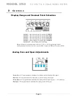
Страница 12: ...play Full Scale Range Range will equate to an analog output value of 5 Vdc or 10 Vdc per Analog Control switch placement Selection is set for 1 count in 5000 2 counts in 10000 and 5 counts in 20000 An...

Страница 13: ...200 Vdc sensors Display Span Adjustments The Display Span Adjustment is used to adjust the digital readout of the 3760 meter the user calibrates the analog output for a specific span value and then a...

Страница 14: ...h 50 mV to 200 Vdc With all switches in the UP position the unit will have the following settings 5 Vdc Analog voltage output full scale 4 20 mA Analog current output full scale The Analog low pass fi...

Страница 15: ...ence Value is determined by the rear rotary switch located behind the rear panel See details after Section 4 calibration TARE Push Push switch When enabled offsets the present sensor signal input to Z...

Страница 16: ...ro Span and Zero re adjustments may need to be repeated to obtain the desired reading Note that the 3760 meter also has independent display adjustment capability to where the digital display can be ad...

Страница 17: ...an potentiometer controls overlaps each step to provide a continuous linear gain of the signal from 50 mVdc to 200Vdc full scale Below is a table of each wide gain steps indicating the nominal low and...

Страница 18: ...een calibrated per the instructions above To access the calibration switch 1 Remove power from the instrument 2 Record the postition of the front panel Wide Span control 0 thru F position 3 Remove the...

Страница 19: ...s When reassembling the fuseholder s make sure L and L are connected together and N and N labeled wires are connected together properly d Mate the rear panel to the enclosure and replace the clamp sli...

Страница 20: ...cnico calificado para evaluar la condici n AVERTISSEMENT Ne remplacez pas le fusible une nouvelle fois si la d faillance se r p te Une d faillance r p t e indique une condition d fectueuse qui ne dis...

Страница 21: ...Model 3760 DC VOLT 4 20mA PANEL METER Page 16 Page left blank...

Страница 22: ...se price to the Buyer ANY PRODUCT FOUND TO BE DAMAGED THROUGH CUSTOMER NEGLIGENCE OR MISUSE MAY BE EXCLUDED FROM ANY AND ALL POLICIES CONTAINED IN THIS DOCUMENT ALL EQUIPMENT TO BE REPAIRED OR REPLACE...

Отзывы: