MODEL 3760
D C VO L T & 4-2 0 mA PA N E L ME TE R
2
C
O N N E C T I O N S
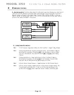
J1 – RCAL Command Connections.
Connection is used to remotely activate the positive
calibration command from the rear panel. When the RCAL terminal is connected to LOGIC COM
via a switch or relay, the 3760 meter will generate 80% of the full scale value as configured.
Fig. 4
RCAL Command
Connections
J1 - RCAL Activation
Connections
Connecting LOG COMMON to the R CAL
terminals will activate an internal voltage
reference in place of the sensor’s signal for
simulated calibration & verification check of
the 3760 settings and input operation.
LOGIC COM
R CAL +
N/O
Switch
J2 - HOLD & TARE Connections.
Connection is used when external control of the "HOLD" and
"TARE" features of the unit are enabled and are controlled by an external switch, PLC or relay. The
LOG COM signal is used to activate the analog HOLD or Analog TARE (offset) to the meter's
display and analog output signals present on J3.
Fig. 5
J1 Logic Controls
HOLD IN
Activates Analog HOLD when connected to LOGIC COMMON
TARE IN
Activates Analog TARE when connected to LOGIC COMMON
TARE ENABLE
Enables remote TARE and disables front panel TARE when connected to LOGIC COMMON
LOGIC COMMON
Connection to enable rear panel features
COMMON MODE FAULT
Logic Output
. True when the
input signal’s Common Mode exceeds specifications.
Push Button, Contact Relay,
Switch…..
LOGIC COM
HOLD
TARE
TARE ENABLE
CM FAULT
Page
8
Common Mode
: Is the voltage level at which the input signal can be "floating" from earth common
which the 3760 can function properly. If this level is exceeeded, the "CMF" (terminal 9, J1) will go true
(to ground), giving the user a remote status of the Common-Mode condition of the 3760 unit.
Static condition of terminal 9 is TTL (+ 5 Vdc).


