

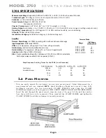


MODEL 3760
D C VO L T & 4-2 0 mA PA N E L ME TE R
4.
CALIBRATION
This section contains the instructions for calibrating the 3760. Included is a functional description of the
instrument front-panel (see Page 1). To perform calibration, proceed as follows.
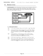
( a )
Connect Sensor and Analog terminals as required. Connect and apply power to the unit. The
front-panel digital display should light indicating the application of the AC input power. Allow
10 minutes of warm up for stabilization of transducer characteristics. Remove the front cover of
the 3760 unit by removing the two small Phillips screws on the front panel. TARE button should
not be activated.
( b )
Center the Zero and Fine Span potentiometers by rotating the potentiometers CW until you feel
the “end stop” or by the number of turns accomplished (Coarse is 22 turns, Fine is 25 turns).
Rotate the potentiometer back to the middle of their range (Coarse 11 turns, Fine 12-13 turns).
This will establish the mid-authority adjustment of the potentiometers.
( c )
Position the front panel switches to the desired settings for the application. Refer to Section 3 for
details.
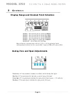
( d )
Relax the sensor or voltage input to “zero” and adjust the Wide Zero and Fine Zero controls
until the meter reading is achieved at the point which will be the “zero” value reference.
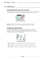
( e )
Once the Zero position has been established, apply a known input to the meter. With the input
active and stable, adjust the Wide Span, Coarse Span and Fine Span controls until the display
reading required is achieved.
( f )
Return the sensor to the "Zero" position and re-adjust the Coarse Zero and Fine Zero controls for
the desired reading or analog output of the unit. Repeat the Span (step e) adjustment as
necessary to achieve the proper reading or analog output. Note that changes in Span (Gain) will
affect Zero. Span and Zero re-adjustments may need to be repeated to obtain the desired reading.
(Note that the 3760 meter also has independent display adjustment capability to where the
digital display can be adjusted independently to the analog output signal of the unit so as to
achieve maximum analog output levels from the meter.)
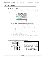
( g )
Once the Zero and the Gain (SPAN) adjustments have been accomplished, if needed -the user
can adjust for Negative non-symmetrical value (as referenced by the positive SPAN value) by
utilizing the front panel Symmetry control when the input to the meter is Negative - adjust the
symmetry control for the correct readout or analog output signal required. Note the Symmetry
control has approx. ± 2 % full scale authority.
( h )
Once completed,
record the position of the "Wide Span" control setting (0 thru F). This setting
position will be used to set the internal RCAL switch as described below under
"Front Panel Calibration (RCAL) setting" instructions.
Display Calibration
The 3760 instrument display has separate adjustment controls that are independent of the
analog output controls - allowing the user to alter the display reading to a value that is suited for the display
while maintaining the flexibility to adjust the analog signal as needed for external devices. In the standard –
default switch position (as marked on the Coarse Span control area), the display has a fixed full scale reading set
by the display range switches of 5000, 10000 or 20000 counts. At theses settings the full scale analog output
signal will be 5 Vdc or 10 Vdc, as selected. To accomplish the display adjustment change, the user would first
set the desired display range and decimal location using the display dip switches, adjust the analog output to the
desired level and then adjust the Display Coarse and Fine span controls for the required digital readout.
(
i
)
R
eplace the front display lens cover to the original position and ensure proper shielding and
grounding
have been done to the meter
.
Page
1
5


