background image

MODEL 3760 

D C  VO L T & 4-2 0 mA   PA N E L  ME TE R 

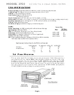
3760 SPECIFICATIONS


Measurement Range:

 Adjustable; 0.050 mV to 200 VDC;  or 4-20 / 4-12-20 mA nominal full-scale. 

Transducer Types: 

DC Voltage or mA Current out (potentiometer, DC to DC LVDT) 

Excitation

:  ± 12.0 Vdc (24 Vdc), up to 50 mA. 

Power Supply: 

Voltage 90 - 250 VAC, 47 -63 Hz

Amplifier 
Normal - Mode Range:

 ±5 V RMS operating; ±28 V without instrument damage  

Input Impedance:

 Differential 200 kΩ 

Offset

: vs. Temperature: ±30 ppm µV/°C; vs. Time: ±10 ppm/month 

Gain Accuracy:

 Limited only by calibration accuracy 

Gain Stability:

 vs. Temperature: ±30 ppm/°C; vs. Time: ±10 ppm/month 

Linearity

: better than ± 0.03% of full scale 

Filter

: 3-pole modified Butterworth; 3 dB down at 2 Hz, 20 Hz or 200 Hz; selectable. 


Fast output always enabled, 5 KHz response (J3 Pin 3). 

Common Mode

:


 Range  

C-M Range 

(V f.s.) (+/- V) 

0.050 - 0.400 

 5 

0.400 - 3.200 

40 

3.200 - 25.00 

200 

25.0 0 - 200.0 

200


Step-Response Settling Times for the 3760 (in milliseconds)


 3db Frequency 

 To within 1%   within .1%     within .02%


 Fast Output 

5000 Hz 

  0.14 

0.10 

0.08 

 Selectable Output 

   200 Hz 

  3.7 

5.0 

5.6 

    20 Hz 

  37 

50 

56 

  2 Hz 

  370 

500 

560 

1.a  

P

ANEL 

M

OUN TING

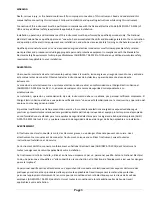
You can easily mo unt the instrument in yo ur o wn precut panel. Cuto ut d imensions for a 

panel-mounted 

unit are standard 

DIN

; panel thickness sho uld  no t exceed  6  mm (0.24 

in).S i mp l y   u n s c r e w   t h e   t w o   r e a r - p a n e l   C L A M P   S C R E W S   a n d   s l i d e   t h e   C L A M P  
SLIDES rearward s o ut o f their groo ves (T HE FRONT  B EZEL NEED NOT B E REMOVED). 
Insert the unit through the panel cutout, 

from the front of the panel 

(if  t h e   u n i t   h a s  r u b b e r  

fe e t ,   t h e s e   wi l l   ha v e   t o   b e   r e mo v e d ) .   T h e n   r e i n s t a l l   t h e   CLAMP SLIDES, and tighten the 
CLAMP SCREWS until the instrument is securely mo unted. 

Page 

6


         Consumption 10 Watts

Physical Parameters: 

5. 68” W x 2. 84” H x 7. 06” D; weight - 3. 25 Lbs.

Analog Output:

 selectable; ± 5, ±1 0 VDC, 4 -20 mA or 4 -12 -20 mA (20 % over -range on voltage outputs only) 

Operating Temperature:

 0 to +55 Degrees C, 5 to 95% relative humidity, non-condensing

Altitude:

 2000m (6560 ft) maximum

Installation Category:

 Installation Category II, Pollution Degree 2

Содержание 3700 Series

Страница 1: ...MODEL 3760 DC VOLTAGE CONDITIONER SB 1 1 INSTRUCTION MANUAL 3700 Instrument Series...

Страница 2: ...nto de este instrumento debe ser realizada por personal calificado solamente El C digo El ctrico Nacional define a una persona calificada como una que est familiarizada con la construcci n y operaci n...

Страница 3: ...lektrische Sicherheitsauflagen f r Angestellt Arbeitspl tze ANSI NFPA 70E 2012 der Vereinigten Staaten und alle zus tzlichen Arbeitsplatzsicherheitsauflagen folgen die auf Ihre Installation anwendbar...

Страница 4: ...ue el material aislante no tenga rajaduras Reemplace de inmediato cualquier parte defectuosa Mesures de S curit Les mesures de s curit suivantes doivent tre prises chaque fois qu un type de connexion...

Страница 5: ...sein wenn Sie Anschl sse an den Stromkreisen durchf hren Stellen Sie sicher da das Ger t AUSgeschaltet ist bevor Sie an der r ckw rtigen Konsole Me f hler anschlie en Pr fen Sie vor jedem Gebrauch al...

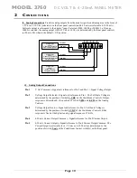
Страница 6: ...it scaling up to 199950 independent of the analog full scale signal The Model 3760 can be calibrated by the two point dead weight process involving known zero and full scale input parameters A conveni...

Страница 7: ...0 in milliseconds 3db Frequency To within 1 within 1 within 02 Fast Output 5000 Hz 0 14 0 10 0 08 Selectable Output 200 Hz 3 7 5 0 5 6 20 Hz 37 50 56 2 Hz 370 500 560 1 a PANEL MOUNTING You can easily...

Страница 8: ...ARE J1 5 TARE ENABLE J1 6 LOGIC COM J1 7 R CAL J1 8 N C J1 9 CM FAULT J1 10 N C No connection No connection Input Analog Hold command Input Analog TARE command External TARE enable input Logic Common...

Страница 9: ...n external switch PLC or relay The LOG COM signal is used to activate the analog HOLD or Analog TARE offset to the meter s display and analog output signals present on J3 Fig 5 J1 Logic Controls HOLD...

Страница 10: ..._ SHIELD EXC COMMON Linear Potentiometer Sensor Linear Potentiometer With Uni Directional output mA _ EXCITATION EXCITATION SIGNAL SIGNAL _ _ SHIELD EXC COMMON mA _ Linear Sensor Linear Transducer Wit...

Страница 11: ...SIGNAL SIGNAL SIGNAL SIGNAL SIGNAL J3 Analog Output Connections Pin 1 V Out Common Signal out reference for Pin 2 and Pin 3 Signal Voltage Output Pin 2 Voltage Output Selected Signal out reference to...

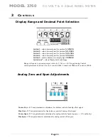
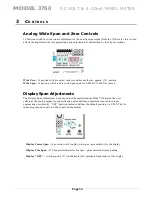
Страница 12: ...play Full Scale Range Range will equate to an analog output value of 5 Vdc or 10 Vdc per Analog Control switch placement Selection is set for 1 count in 5000 2 counts in 10000 and 5 counts in 20000 An...

Страница 13: ...200 Vdc sensors Display Span Adjustments The Display Span Adjustment is used to adjust the digital readout of the 3760 meter the user calibrates the analog output for a specific span value and then a...

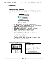
Страница 14: ...h 50 mV to 200 Vdc With all switches in the UP position the unit will have the following settings 5 Vdc Analog voltage output full scale 4 20 mA Analog current output full scale The Analog low pass fi...

Страница 15: ...ence Value is determined by the rear rotary switch located behind the rear panel See details after Section 4 calibration TARE Push Push switch When enabled offsets the present sensor signal input to Z...

Страница 16: ...ro Span and Zero re adjustments may need to be repeated to obtain the desired reading Note that the 3760 meter also has independent display adjustment capability to where the digital display can be ad...

Страница 17: ...an potentiometer controls overlaps each step to provide a continuous linear gain of the signal from 50 mVdc to 200Vdc full scale Below is a table of each wide gain steps indicating the nominal low and...

Страница 18: ...een calibrated per the instructions above To access the calibration switch 1 Remove power from the instrument 2 Record the postition of the front panel Wide Span control 0 thru F position 3 Remove the...

Страница 19: ...s When reassembling the fuseholder s make sure L and L are connected together and N and N labeled wires are connected together properly d Mate the rear panel to the enclosure and replace the clamp sli...

Страница 20: ...cnico calificado para evaluar la condici n AVERTISSEMENT Ne remplacez pas le fusible une nouvelle fois si la d faillance se r p te Une d faillance r p t e indique une condition d fectueuse qui ne dis...

Страница 21: ...Model 3760 DC VOLT 4 20mA PANEL METER Page 16 Page left blank...

Страница 22: ...se price to the Buyer ANY PRODUCT FOUND TO BE DAMAGED THROUGH CUSTOMER NEGLIGENCE OR MISUSE MAY BE EXCLUDED FROM ANY AND ALL POLICIES CONTAINED IN THIS DOCUMENT ALL EQUIPMENT TO BE REPAIRED OR REPLACE...

Отзывы: