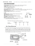
MODEL 3760
D C VO L T & 4-2 0 mA PA N E L ME TE R
3
Controls
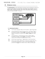
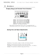
Analog Control Settings
Front panel controls configure the main parameters of the Signal conditioner for input type,
mode of the analog output signal, low pass filter characteristics and full scale voltage input
range.
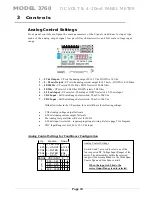
1 – 5 Vdc Output -
UP sets the analog output FS to 5 Vdc, DOWN is 10 Vdc
2 – 4 - 20 mA Output -
UP sets the analog current output for 4-20 mA , DOWN is 4-12-20ma
3 – 20/200 Hz -
UP selects 20 Hz filter. DOWN selects 200 Hz filter
4 – 20/2 Hz -
UP selects 20 Hz filter. DOWN selects 2 Hz filter
5 – 4-20 mA Input –
UP selects 4-20 ma Input. DOWN selects 4-12-20 mA Input
6 – VDC Input –
Full Scale Range Select switch, 50 mV to 200 Vdc
7 – VDC Input –
Full Scale Range Select switch, 50 mV to 200 Vdc
With all switches in the UP position, the unit will have the following settings:
•
5 Vdc Analog voltage output full scale
•
4-20 mA Analog current output full scale
•
The Analog low pass filter will be set for 20 Hz
•
4-20 mA input is selected –
requires proper input wiring. Refer to page 5 for diagram
•
VDC Input Range set for 3.20 to 25.0 Vdc input
Analog Control Settings for Conditioner Configuration
1– VDC OUT
2 – mA OUT
3 – FILTER
4 – FILTER
5 – mA IN
5
4-20
20 Hz
20 Hz
4-20
Up
10
4-12-20
200 Hz
2 Hz
4-12-20
Down
Function
RANGE
VDC INPUT
6 7
0.05 – 0.40
0
.40 – 3.20
3.20 – 25.0
25.0 – 200.0
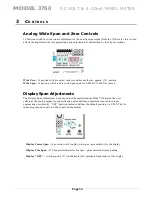
Analog Control Settings
Switch 6 and 7 are used to select one of the
four expected DC Voltage Input Ranges of the
meter. The adjustability within the selected
range will be accomplished via the Wide Span,
Coarse Span and Fine Span controls.
When the input is 4-20mA,
the
correct input R
ange is
auto-
se
lected
Page
13
1
2
3
4


