
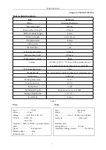


USER’S MANUAL
16
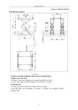
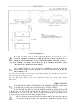
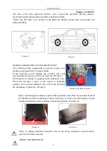
Chapter 4 INSTALLAION
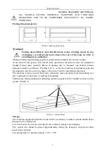
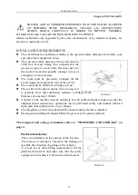
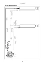
OIL PIPE CONNECTION:
Follow “oil pip connection diagram “to connect the oil pipes.
Only skilled and authorized person is allowed to perform the operations. And pay
particularly attention to the protection of oil pipe head.
-Following oil pipe number to lead the oil pipe out from the oil make-up stop valve “H”
of control box and then connect it to the cylinder. (Refer to “oil pipe connection
diagram”)
-When connect oil pipe, pay attention to the protection of oil pipe tie-in to prevent
impurities from entering hydraulic circuit.
When connecting the oil pipe, take careful of the mistake of each oil pipe number.
During the standard installation, control box is in the nearside of vehicle-entering
direction. If placed on the right side should adjust relevant oil pipe.
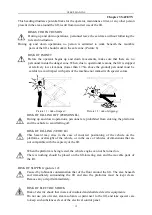
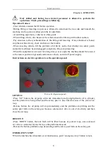
COMPRESSED AIR PIPE CONNEVTION:
Follow “air pipe diagram “to connect air loop.
Only skilled and authorized person is allowed to perform the operations.
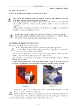
-Connect Φ8×6 compressed air supply pipe to the air supply jaws of solenoid air
valve inside the control box. (Picture18)
-Follow “air pipe diagram “to lead the compressed air pipe out from solenoid air valve
and then connect it to the uplifted-pawl air valve. (Picture 19)
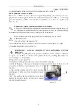
-Pay attention to the protection of windpipe tie-in to prevent impurities from entering
compressed air circuit.
-Connect compressed air hose to the extra-installed grease separator which is in front of
control box to prolong the lift of pneumatic components and the reliability of action.
In the process of air hose installation, the air hose not be folded or tied to avoid that
the air loop is not smooth or it is jammed.
Before leading the compressed air supply pipe to the air supply jaws of pneumatic
electromagnetic valve inside the control box, should extra install grease separator to
separate compressed air, avoiding the failure of pneumatic cell action.
Picture 18
Picture 19
Содержание LJS7035
Страница 1: ...USER S MANUAL 1 Small scissor Lift LJS7035 USER USER S S MANUAL MANUAL Operation Manual Instruction ...
Страница 26: ...USER S MANUAL 26 Oil pipe connection diagram ...
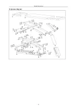
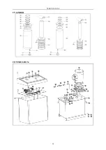
Страница 27: ...USER S MANUAL 27 Explosion diagram ...
Страница 28: ...USER S MANUAL 28 CYLINDER CONTROL BOX ...
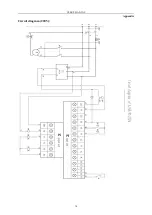
Страница 29: ...USER S MANUAL 29 Appendix Circuit diagram 380V ...
Страница 30: ...USER S MANUAL 30 Appendix Circuit diagram 220V ...


