VLASE
TM
IR
14
1
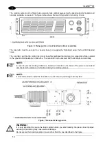
The marking system can be fitted inside a special rack cabinet equipped with special support shoulders and
handles, available on request. The figure below shows the mounting points for mounting in rack:
Figure 6: Fixing points on rack handles (cabinet assembly).
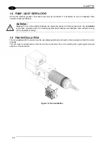
The resonator must be secured to a special base (not supplied by Datalogic) using the four M6 threaded
holes.
The resonator, just like the control rack, must be safely positioned and secured on a special surface, parallel
to the ground and absolutely vibration-free. The resonator can be secured both horizontally and vertically.
NOTE:
In order to prevent marking distortions, install a vibrometer on the base of the piece to be marked
and check for the absence of vibrations during the marking process.
NOTE:
It is recommended to install the resonator on a micrometer positioning Z-axis system!
Figure 7: Resonator fixing points
WARNING!
It is very important to secure the laser system before you start marking the piece since improper
securing or positioning may cause serious damage.
Do not secure the marking system in a way other than the one described in the figure.
Содержание VLASE IR 1PWX-TLS2
Страница 1: ...USER S MANUAL VLASETM IR ...
Страница 34: ...VLASETM IR 34 2 2 6 CONNECTION EXAMPLES Figure 27 Connection examples ...
Страница 59: ...USE AND OPERATION 59 4 Edit Filling properties such as filling type interline etc using the Properties browser ...
Страница 78: ...VLASETM IR 78 6 6 4 RACK HANDLES Handles for rack fastening are available on request Figure 64 Rack handles ...
Страница 85: ...85 EXTERNAL LABEL PLACING Figure 67 Positioning of external labels rack ...
Страница 86: ...86 Figure 68 Positioning of external labels resonator ...
Страница 90: ...90 BLOCK DIAGRAM VLASETM SAFETY LOGIC DETAILS FOR AUTOMATIC PRODUCTION LINE ...
Страница 108: ...108 APPENDIX G MECHANICAL DRAWINGS ...
Страница 109: ...109 NOTE Please refer to Datalogic website for detailed drawings ...
Страница 112: ......


