VLASE
TM
IR
20
2
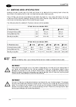
2.3 MARKING AREA SPECIFICATION
Datalogic provides a wide range of F-Theta scan lenses to be attached to the scanning head to focus the
laser beam in the marking field, in order to achieve high-resolution marking results.
These F-Theta scan lenses are available to best-match the object (i.e.: logo; string; 2D matrix; etc.) to be
marked and fit the standard Datalogic Scanning Head; further solutions using different models of F-Theta
scan lenses and scanning heads will be considered upon request.
The table below lists the standard F-Theta scan lenses currently available:
F-Theta Scan Lens diameter: M39
F-Theta Scan lens
= 160S
= 254S
Working Distance (WD)
mm
183 ± 5
280 ± 4
Fixing Distance (FD)
mm
154 ± 6
257 ± 5
Marking Area (MA)
mm
2
100 x 100
140 x 140
F-Theta Scan Lens diameter: M85
F-Theta Scan lens
= 100L
= 160L
= 254L
= 330L
= 420L
Working Distance (WD)
mm
99 ± 1
176 ± 2
296 ± 5
388 ± 6
494 ± 8
Fixing Distance (FD)
mm
98 ± 2
170 ± 3
329 ± 6
427± 7
533 ± 9
Marking Area (MA)
mm
2
50 x 50
110 x 110
180 x 180
220 x 220
285 x 285
NOTE:
Definition of Marking Area:
square marking field measured on black anodized aluminium plate
.
WARNING!
This product was designed to use only certain configurations of F-Theta lens and marking field. If
your needs are not satisfied by the currently available F-Theta lens configurations please contact
Datalogic for a solution. The use of other F-Theta lenses or operation outside the specified marking
field for a certain F-Theta lens configuration can lead to damage of the F-Theta lens, scanning head
or laser source. Such damage is not covered by warranty!
WARNING!
For each F-Theta lens configuration Datalogic recommends the use of certain adapter. This adapter
ensures that residual back reflections caused by the F-Theta lens do not damage the scanning head
optics. The removal of such adapter or its incorrect use (for example incomplete threading, use of
another F-Theta lens adapter, etc.) can lead to damage of the F-Theta lens, scanning head or laser
source. Such damage is not covered by warranty!
Содержание VLASE IR 1PWX-TLS2
Страница 1: ...USER S MANUAL VLASETM IR ...
Страница 34: ...VLASETM IR 34 2 2 6 CONNECTION EXAMPLES Figure 27 Connection examples ...
Страница 59: ...USE AND OPERATION 59 4 Edit Filling properties such as filling type interline etc using the Properties browser ...
Страница 78: ...VLASETM IR 78 6 6 4 RACK HANDLES Handles for rack fastening are available on request Figure 64 Rack handles ...
Страница 85: ...85 EXTERNAL LABEL PLACING Figure 67 Positioning of external labels rack ...
Страница 86: ...86 Figure 68 Positioning of external labels resonator ...
Страница 90: ...90 BLOCK DIAGRAM VLASETM SAFETY LOGIC DETAILS FOR AUTOMATIC PRODUCTION LINE ...
Страница 108: ...108 APPENDIX G MECHANICAL DRAWINGS ...
Страница 109: ...109 NOTE Please refer to Datalogic website for detailed drawings ...
Страница 112: ......

