VLASE
TM
IR
50
4
4 USE AND OPERATION
4.1 TURNING ON SEQUENCE
Before turning on the marking system, be sure that the system is connected as previously described. Check
presence of voltage power supply connection, interlock connector and Command Box connector. Check that
KEY
and
ENABLE
commands on the rack front panel are disabled (see Figure 19 and Figure 20).
1
ST
:
turn on the main switch at the back of the control rack:
Figure 54: Power on.
SIGNAL
STATUS
EXT_KEY
OFF
EXT_ENABLE_A
OFF
EXT_ENABLE_B
OFF
During booting-up, the status LED on the rack front panel will be blinking green.
Wait until booting-up finishes. The status LED on the rack will be steady green.
Figure 55: Status LED display
.
Содержание VLASE IR 1PWX-TLS2
Страница 1: ...USER S MANUAL VLASETM IR ...
Страница 34: ...VLASETM IR 34 2 2 6 CONNECTION EXAMPLES Figure 27 Connection examples ...
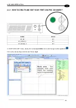
Страница 59: ...USE AND OPERATION 59 4 Edit Filling properties such as filling type interline etc using the Properties browser ...
Страница 78: ...VLASETM IR 78 6 6 4 RACK HANDLES Handles for rack fastening are available on request Figure 64 Rack handles ...
Страница 85: ...85 EXTERNAL LABEL PLACING Figure 67 Positioning of external labels rack ...
Страница 86: ...86 Figure 68 Positioning of external labels resonator ...
Страница 90: ...90 BLOCK DIAGRAM VLASETM SAFETY LOGIC DETAILS FOR AUTOMATIC PRODUCTION LINE ...
Страница 108: ...108 APPENDIX G MECHANICAL DRAWINGS ...
Страница 109: ...109 NOTE Please refer to Datalogic website for detailed drawings ...
Страница 112: ......

