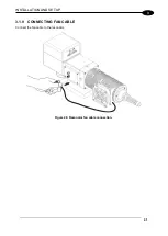
INSTALLATION AND SET UP
37
3
3.1.4 CONNECTING THE OPTICAL FIBER TO THE CONTROL RACK
Follow the steps listed here below to connect the optical fiber to the control rack:
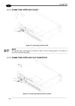
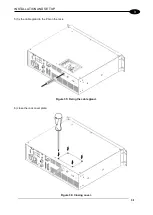
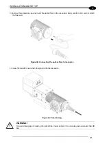
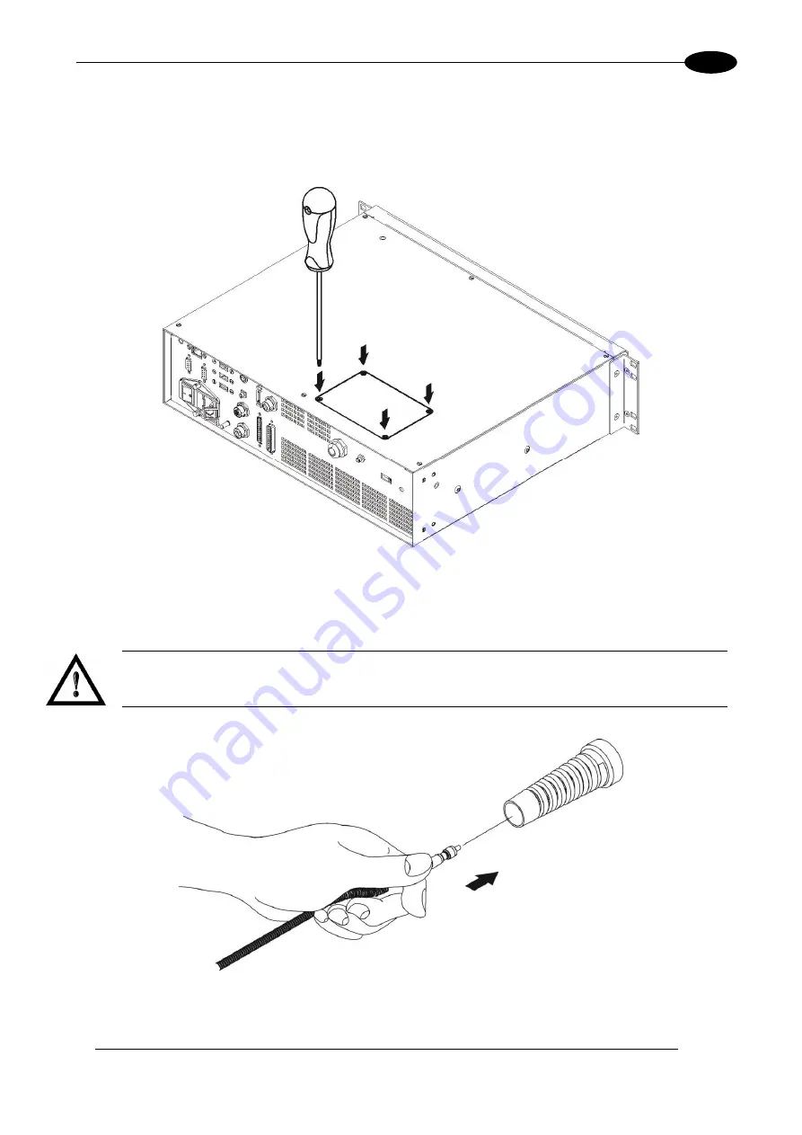
1) unscrew the four screws holding the cover plate on the rack.
Figure 31: Removing the cover plate from the rack.
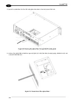
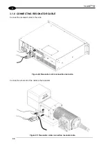
2) insert the optical fiber into the cable gland without removing its protection cap.
WARNING!
The insertion of the optical fiber is a delicate operation. You must make sure that the optical fiber is
protected by its cap during insertion through the cable gland to avoid damaging or dirtying it.
Figure 32: Passing the optical fiber through the cable gland.
Содержание VLASE IR 1PWX-TLS2
Страница 1: ...USER S MANUAL VLASETM IR ...
Страница 34: ...VLASETM IR 34 2 2 6 CONNECTION EXAMPLES Figure 27 Connection examples ...
Страница 59: ...USE AND OPERATION 59 4 Edit Filling properties such as filling type interline etc using the Properties browser ...
Страница 78: ...VLASETM IR 78 6 6 4 RACK HANDLES Handles for rack fastening are available on request Figure 64 Rack handles ...
Страница 85: ...85 EXTERNAL LABEL PLACING Figure 67 Positioning of external labels rack ...
Страница 86: ...86 Figure 68 Positioning of external labels resonator ...
Страница 90: ...90 BLOCK DIAGRAM VLASETM SAFETY LOGIC DETAILS FOR AUTOMATIC PRODUCTION LINE ...
Страница 108: ...108 APPENDIX G MECHANICAL DRAWINGS ...
Страница 109: ...109 NOTE Please refer to Datalogic website for detailed drawings ...
Страница 112: ......


