


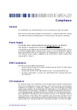


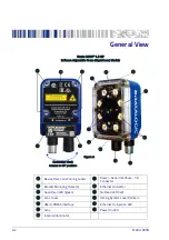


General View
Product Reference Guide
xv
Matrix 300N™ 1.3 MP
Manual Adjustable Focus Models
Connector block
rotates to 90° position
Figure B
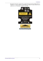
Device Class and Warning Labels
Internal Illuminator
Bracket Mounting Holes (4)
Power - Serial Interfaces - I/O
Connector
Good Read LED (green)
Ethernet Connector
Lens Cover
No Read LED (red)
HMI X-PRESS Interface
Aiming System Laser Pointers
Lens
Ethernet Connection LED
Focus Adjustment Screw
Power On LED
Содержание Matrix 300N
Страница 1: ...Matrix 300N Product Reference Guide Image Based Reader...
Страница 72: ...Installation 56 Matrix 300N Figure 28 Mounting Bracket Overall Dimensions mm inch...
Страница 86: ...CBX Electrical Connections 70 Matrix 300N Figure 43 ID NET Network Connections with Common Power Branch Network...
Страница 87: ...ID NET Interface Product Reference Guide 71 Figure 44 ID NET Network Connections with Common Power Star Network...
Страница 91: ...Inputs Product Reference Guide 75 Figure 48 NPN External Trigger Using Matrix 300N Power...
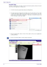
Страница 153: ...Reader Configuration Product Reference Guide 137 Figure 84 Decoding Results OK...
Страница 180: ...ID NET Master ID NET Slave 1 ID NET Slave 1 Software Configuration 164 Matrix 300N...
Страница 182: ...Software Configuration 166 Matrix 300N Open the cloned application job...
Страница 216: ...DPM Data Matrix and QR codes on metal surfaces Non polarized Polarized Illuminators 200 Matrix 300N...
Страница 246: ......
Страница 247: ......


