VLT
®
6000 HVAC
8
MG.60.G2.02 - VLT is a registered Danfoss Trademark
7.
Press “-” key until ‘6’ counts down to ‘0’ and
setting for
Ramp Up Time
reads ‘100 s.’
8.
Press OK key to enter new value into drive
controller.
9.
Press Display key to return to normal display.
Extended Menu
In some applications, the Quick Menu items will not
set up all the desired characteristics of the drive. To
access all VLT 6000 parameters, including the Quick
Menu parameters, press the Extend Menu key.
NOTE:
NOTE:
NOTE:
NOTE:
NOTE:
Programming of parameter functions available
through Extended Menu is done in accor-
dance with same procedure as described for Quick
Menu functions.
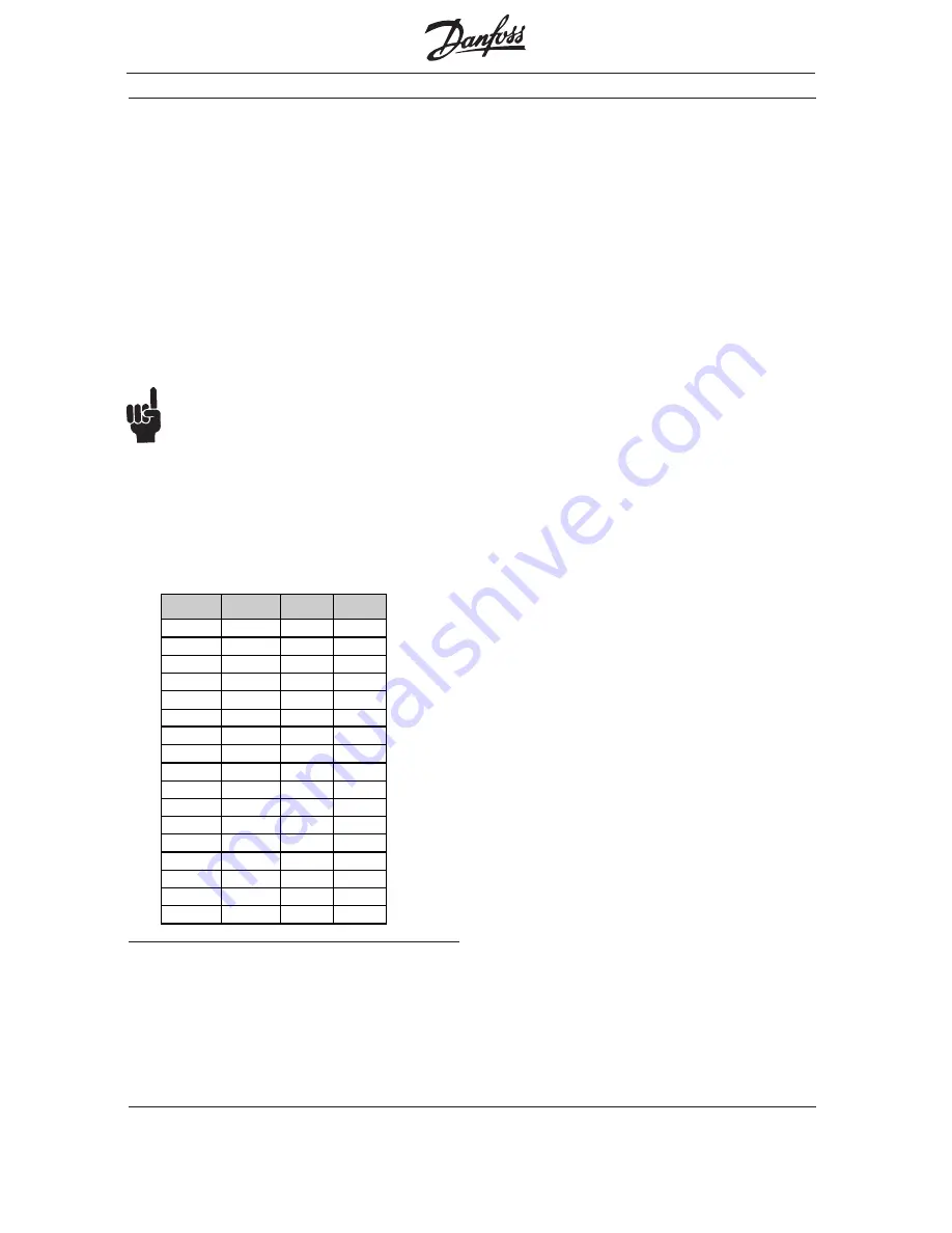
HP/kW Conversion
A conversion index for determining kW and HP
ratings is shown in Table 2.
Table 2 HP to kW Conversion Index
■
■
■
■
■
VLT 6000 Functional Features
kW
HP
kW
HP
0.25 0.33 45 60
0.37 0.5 55 75
0.55 0.75 75 100
0.75 1.0 90 125
1.1 1.5 110
150
1.5 2.0 132
175
2.2 3.0 160
200
3.0 --- 200
300
4.0 5.0 250
---
5.5 7.5 300
---
7.5 10 315
350
11 15 355
450
15 20 400
500
18.5 25 450 600
22 30
30 40
37 50
The FLN protocol built into the VLT 6000 frequency
converter allows programming of numerous features
and monitoring of the drive via the serial bus and the
standard RS-485 port. The VLT 6000 also has the
capability to control closed or open loop systems on
its own and has been designed specifically for HVAC
applications. Always accessible in real-time are the
system status, what the motor and drive are doing,
and if there are any problems. The VLT 6000
continuously monitors all aspects of motor and drive
status and issues alarms or warnings for adverse
conditions.
The FLN interacts with the drive based upon a point
map database and the selected interface strategy.
Many, but not all, drive features are accessible
through the point map. See the
VLT 6000 Operating
Instructions
for more drive details. Table 8 lists the
map points and Table 9 supplies definitions. Below is
a review of some frequently used drive features and
the associated point map numbers.
Drive Operation (03-14)
These points provide the FLN with operational status
information such as output frequency, motor current,
output voltage, power and energy. The run time in
hours that power has been supplied to the motor is
also stored for display, along with cumulative energy
used in kWh.
Motor and Drive Thermal Protection (15, 16, 18)
The motor and drive are protected against thermal
overload. The percentage of thermal load is dis-
played. Point 18 indicates if either the motor or drive
thermal limit has been exceeded.
Set-up 1 - 4 (17) (29)
The drive is capable of maintaining four independent
program set-ups. Each set-up supports independent
point map configurations. Seasonal changes, various
acceleration or deceleration rates, or other operation
modes can be accommodated. Point 17 indicates
which setup is active. The set-up change is
programmed through the drive’s keypad or digital I/
Os. Day/night operation is implemented in the point
map (29) but is not used in this application.


