W E B S T A T I O N M a n u a l P a g e 14
6
USB / LINE INPUT MODULES 3-4-5
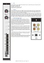
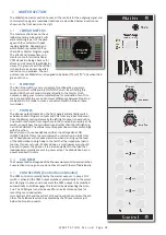
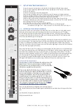
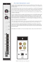
The input modules switches & controls of the Webstation mixer have the following functions:
Each of Modules 3 thru 5 have two selectable inputs. The two types of inputs consist of an USB in
-
put and a stereo line input. In the lower USB switch position, the module is a stereo module. When
the USB is switched off (up position), you also have a stereo line level input to feed the Master
buss, Cue buss and Voice tracking buss.
6.1
GAIN
With the gain control (the first control knob below the modules number), the source input level
can be adjusted to the required internal mixer level. This control adjusts both the USB input and
the stereo Line inputs with the same control depending on the switch position.
6.2
STEREO LINE
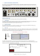
The stereo line input is a high impedance input ( >10 kOhm) for connecting the stereo line level
outputs of devices such as CD players/MP3 players etc.
6.3
USB
The USB stereo signal comes directly from one of the 3 stereo USB channels from your PC play-out
software. These are already assigned in the Mixer to module 3, 4 and 5 by D&R.
6.4
CUE/COMMUNICATION BUSS
The stereo CUE switch (Pre Fade Listening) allows you to check the signal before you raise your
channel fader up and mix it with other signals in the mixer.
Another smart function is that this CUE bus can be used for
communication.
If you push a DJ’s Cue
(let’s say channel one) and if you then push the Telco Cue, the DJ as well as the caller can hear each
other outside the broadcast and even you, sitting behind the desk on the monitor speakers.
Note:
Levels need to be carefully set to avoid feedback and overdrive of circuits.
The Cue switch also sends out HID signal over USB that can be programmed to do specific func
-
tions in your play-out system. In the Control section of the manual we will explain how.
6.5
ON
The ON switch also sends out HID signal over USB that can be programmed to do specific func
-
tions in your play-out system. In the Control section of the manual we will explain this how.
6.6
FADER
Final audio level control is the high quality, 100 mm long throw N-Alps channel fader that send
out a control voltage to the internal stereo VCA. The control voltage is also used to detect when
the fader is moved up and sends out a pulse for fader start purposes.
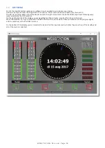
In the software set up there is a setting where you can select if you want and extra 10dB of fader
gain. Then the unity gain position will be at the -10dB position. If you are a person that sweeps the
fader fully up and down, then do not select the extra fader gain of 10dB and choose for a unity gain
position in the fully up position of the fader. A software page will be shown further in this manual to
customize the Webstation to your needs with instructions how to do that.
6.7
SETTING UP THE USB MODULES
Actually there is not so much you can do concerning routing of the incoming USB signals. The ON
switches connect the incoming stereo signals sent by the play-out system 1-3 to channel 3, 4 and 5.
The routing inside the PC software is done automatically and described in more detail below. In the
Block diagram (in the brochure and in this manual) you can see that the mixers USB output signal
1 (all stereo) is the program signal and sent to the USB-1 buss. It is a PROG POST signal, it means a
post channel stereo fader signal is sent to the USB connector and to your PC.
6.8
USB OUTPUTS
There are 4 stereo USB signals sent to your PC through the USB connector on the back of your con
-
sole.
USB-1 = Main program signal.
USB-2 = Clean feed
USB-3 = Voice track signal
USB-4 = VoIP signal
An audio application needs to run on your PC to be able to see the levels. Otherwise trial and error is
the only way. A free downloadable tool can be found here
http://minorshill.co.uk/pc2/testgen.html
The return USB signal coming from the PC is fixed but can be adjusted with the webstation’s module
gain controls.


