W E B S T A T I O N M a n u a l P a g e 13
5.9
INPUT CONNECTORS
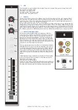
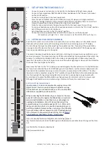
On the back of modules 1 and 2, you find four connectors for each mod
-
ule. The stereo line input uses Cinch female type connectors.
Being un-balanced, the shield and (-) or out of phase signal wire need to
be connected together and seen as ground during installation.
5.10
INSERT
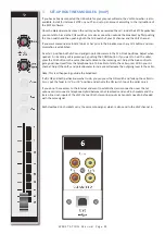
This ring/tip/sleeve stereo jack socket lets you insert signal processors
such as compressors/gates or special voice processing units to improve
your voice timbreto become the ultimate announcer/D.J.
The Ring of the stereo jack sends the PRE-FADER channel signal and the
Tip accepts the return signal.
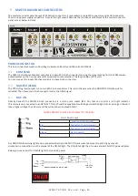
Below on the right you see the type of cable you need when your proces
-
sor has jack in and outputs. Connect the tip from the stereo cable to the
tip of one of the mono jacks and the ring of the stereo cable to the tip of
the other mono jack.
Now insert the stereo jack into the Webstation’s insert and connect the
mono jack that produces a hum when the tip is touched by your finger (and
the related channel fader is open) into the processors output. The other
mono jack should be inserted into the processors input.
In case your processor has XLR inputs connect the tip of the stereo jack to
pin 2 of the Female XLR and short pin 1 and 3 with each other and con
-
nect to ground (sleeve). This also goes for the other Male XLR. Connect the ring of the stereo jack (which sends signals) to a
male XLR pin2. Short here pin 1 and 3 and solder to ground (sleeve). This has to be done because the insert is not balanced.
See below the cable type you need.
5.11
MICROPHONE INPUT
The Mic input is a balanced female XLR type connector., see the left connector below
that should go into your mixer and your mic cable should end in a male XLR as seen
on the right section of the picture.
1=Ground/shield
2=Hot (in phase)
3=Cold (out of Phase).


