


166
Standalone MMC Hardware Manual
CE and EMC Guidelines
version 15.1
Danaher Motion
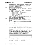
4°C in a range of -200° to 266°C. Worst case tests with a JK thermocouple module
have caused momentary disturbances no greater than + or - 1 mV over a 100 to 1.
11.8
Using CE/EMC and Non-CE/EMC Modules
There are several issues that must be considered when using CE/EMC compliant and
Non-CE/EMC compliant Modules. This document addresses these issues.
Module Identification
- To determine whether a module is CE/EMC or Non-CE/EMC,
look at the gray Unit Tag located on the side of the plastic module case. CE/EMC
modules will have “CE” or “EMC” printed near the “MAX. AMBIENT TEMP.”
specification. Non-CE/EMC will not have “CE” or “EMC” printed in this location.
Grounding
- Due to differences in shielding requirements, it is extremely important to
follow proper shielding guidelines for a given module. Failure to do so may result in
intermittent operation in noisy environments.
For modules that have an SPG terminal and/or one or more SHIELD terminal, perform
the following:
•
For CE/EMC modules, do not connect the SPG terminal or SHIELD terminals to
the system’s Single Point Ground
•
For Non-CE/EMC modules, connect the SPG terminal, or a SHIELD terminal, to
the system’s Single Point Ground
CE/EMC CSM and RSM Modules
- Using a CE/EMC CSM, RSM, or CSM/CPU
(PiC90) with certain Non-CE/EMC analog modules may cause intermittent operation.
Follow these guidelines for determining the type of CSM, RSM, or CSM/CPU that
should be used in a particular rack:
•
If your rack contains one or more Non-CE/EMC modules that perform D/A conver-
sion or provide an Encoder interface, you must use a non-CE/EMC CSM, RSM, or
CSM/CPU (PiC90).
•
If your rack contains one or more Non-CE/EMC modules that perform D/A conver-
sion or provide an Encoder interface, you must use a non-CE/EMC CSM, RSM, or
CSM/CPU (PiC90).
NOTE
To assure compliance with the low voltage directive, it is necessary to follow
installation instructions in the controller Hardware Manual. Also refer to any
instructions specific to individual control modules.
IMPORTANT
Failure to follow these guidelines may result in undesired system perfor-
mance.
NOTE
CE indicates compliance to both the EMC and low voltage directives. EMC
indicates compliance to the EMC directive.
Содержание Standalone MMC
Страница 4: ......
Страница 8: ...8 Standalone MMC Hardware Manual Table of Contents version 15 1 Danaher Motion ...
Страница 32: ...32 Standalone MMC Hardware Manual Installation Operation Maintenance version 15 1 Danaher Motion ...
Страница 94: ...94 Standalone MMC Hardware Manual Standalone MMC Control version 15 1 Danaher Motion ...
Страница 130: ...130 Standalone MMC Hardware Manual MMC Ethernet TCP IP Option Module version 15 1 Danaher Motion ...
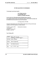
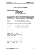
Страница 168: ...168 Standalone MMC Hardware Manual CE and EMC Guidelines version 15 1 Danaher Motion 11 9 Declarations of Conformity ...
Страница 169: ...Standalone MMC Hardware Manual 169 Danaher Motion version 15 1 CE and EMC Guidelines ...
Страница 170: ...170 Standalone MMC Hardware Manual CE and EMC Guidelines version 15 1 Danaher Motion ...
Страница 171: ...Standalone MMC Hardware Manual 171 Danaher Motion version 15 1 CE and EMC Guidelines ...
Страница 172: ...172 Standalone MMC Hardware Manual CE and EMC Guidelines version 15 1 Danaher Motion ...


