Page 46 of 62
SK2014
‐
SON
‐
002
‐
TechMnl
‐
FMCD
‐
003
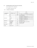
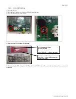
C.4.3.
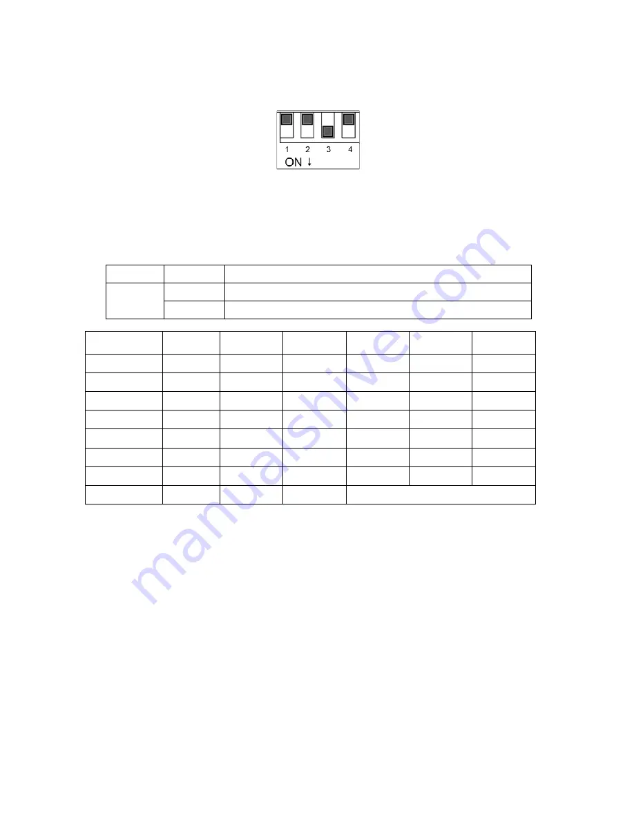
Onboard
Configuration
There
is
1
DIP
switch
set
on
the
PCB:
DIPB
(4
positions)
SW1:
configured
for
different
modulating
signal.
SW2
–
SW4:
brushless
DC
fan
motor
configuration.
Code
State
Description
SW1
0
PCB
configured
for
0~5VDC
modulating
signal
input.
1
PCB
configured
for
0~10VDC
modulating
signal
input.
MODEL
SW2
SW3
SW4
Hi
Med
Low
FMCD
‐
04
0
0
0
700
600
500
FMCD
‐
06
0
0
1
930
700
600
FMCD
‐
12
0
1
0
930
700
600
FMCD
‐
15
0
1
1
1150
800
700
FMCD
‐
18
1
0
0
1300
1100
900
FMCD
‐
20
1
0
1
1100
900
800
FMCD
‐
24
1
1
0
1350
1200
900
Default
RPM
1
1
1
Set
by
customer
requirement
C.4.4.
Control
Logic
Specification
1.
Power
On
Setting
When
any
fan
speed
is
selected,
the
unit
is
turned
on.
When
all
of
the
relays
are
off,
the
unit
is
turned
off.
2.
Swing
/
Louver
When
the
unit
is
turned
on,
the
louver
will
open
to
the
largest
angle
at
100º,
then
move
to
the
operating
angle
at
87
º.
When
the
unit
is
turned
off,
the
louver
will
close.
3.
Signal
Input
When
Auto
speed
is
turned
ON,
the
unit
is
turned
on
and
the
motor
runs
at
200
RPM.
EC
motor
RPM
will
be
changed
by
the
signal
voltage.
Содержание FMCD*ECM series
Страница 11: ...Page 11 of 62 Dimensional drawing for FMCD 20 24 ECM All dimensionsshown in mm ...
Страница 21: ...Page 21 of 62 SK2014 SON 002 TechMnl FMCD 003 C 1 3 Wiring Diagram SK NCFMCD 001 ...
Страница 45: ...Page 45 of 62 SK2014 SON 002 TechMnl FMCD 003 C 4 2 Wiring Diagram SK NCFMCD 002 ...
Страница 62: ...Page 62 of 62 SK2014 SON 002 TechMnl FMCD 003 ...

