Daikin VRV IV-S RXTQ-TAVJU Series Скачать руководство пользователя страница 60

Protection Control

SiUS331604E

47

Functions and Control

4.3

Discharge Pipe Protection Control

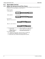
This discharge pipe protection control is used to protect the compressor internal temperature against error or 
transient increase in discharge pipe temperature.

• 

HTdi > 115˚C (239˚F)

• 

Tp > 135˚C (275˚F)

OR

36 Hz Unload

• 

HTdi > 115˚C (239˚F)

• 

Tp > 135˚C (275˚F)

OR

• 

HTdi > 135˚C (275˚F)

• 

HTdi > 120˚C (248˚F) for 10 minutes or more.

OR

• 

HTdi < 110˚C (230˚F)

• 

Tp < 125˚C (257˚F)

&

After 30 seconds

After 20 seconds

• 

HTdi > 130˚C (266˚F)

• 

HTdi > 120˚C (248˚F)

for 90 seconds 
or more.

OR

• 

HTdi < 100˚C (212˚F)

• 

Tp < 110˚C (230˚F)

&

Discharge pipe 
temperature standby

Discharge pipe protection 
control not limited

Compressor upper limit 
frequency: 1-step down from 
current compressor frequency

In discharge pipe temp. 

protection control

When occurring 3 times within 100 minutes, 
the error code 

F3

 is output.

Compressor upper limit frequency: 1-step 
up from current compressor frequency

Tp:    Value of compressor port temperature 

calculated by Tc, Te, and suction 
superheated degree.

HTdi: Value of compressor discharge pipe 

 temperature (Tdi) compensated with 
 outdoor air temperature

Содержание VRV IV-S RXTQ-TAVJU Series

Страница 1: ...Service Manual SiUS331604E RXTQ36 48 60TAVJU Heat Pump 60 Hz...

Страница 2: ...00 F5 3 FXHQ M EDUS391100 F6 2 3 FXAQ P EDUS391502 F7 4 7 FXLQ M FXNQ M EDUS391000 F12 2 3 FXTQ PA 2 Specifications Outdoor Unit EDUS331608 R 2 4 RXTQ T 3 Specifications Energy Recovery Ventilator EDU...

Страница 3: ...ant Circuit 6 1 Refrigerant Circuit 7 1 1 RXTQ36TAVJU 7 1 2 RXTQ48TAVJU 9 1 3 RXTQ60TAVJU 11 2 Functional Parts Layout 13 2 1 RXTQ36TAVJU 13 2 2 RXTQ48TAVJU 14 2 3 RXTQ60TAVJU 16 Part 3 Remote Control...

Страница 4: ...tion 39 3 3 Defrost Operation 41 3 4 Pump down Residual Operation 42 3 5 Restart Standby 43 3 6 Stopping Operation 43 4 Protection Control 44 4 1 High Pressure Protection Control 44 4 2 Low Pressure P...

Страница 5: ...te Controller 96 2 5 Field Setting of Operation Control Mode 96 3 Field Setting from Outdoor Unit 99 3 1 Capacity Setting 99 3 2 Setting Mode and Monitor Mode 100 3 3 Setting Mode 1 101 3 4 Setting Mo...

Страница 6: ...tivation of Low Pressure Sensor 169 4 22 Inverter Compressor Motor Lock 171 4 23 Outdoor Fan Motor Abnormality 173 4 24 Electronic Expansion Valve Coil Abnormality 175 4 25 Discharge Pipe Temperature...

Страница 7: ...lity Refrigerant System Address Undefined 207 4 50 Defective PCB 209 4 51 Transmission Error between Centralized Controllers 210 4 52 Poor Centralized Controller Combination 212 4 53 Address Duplicati...

Страница 8: ...ding Safety of Workers Warning Do not store the equipment in a room with fire sources e g naked flames gas appliances electric heaters Be sure to disconnect the power cable from the socket before disa...

Страница 9: ...equipment failure Do not mix air or gas other than the specified refrigerant R 32 R 410A R 22 in the refrigerant system If air enters the refrigerating system excessively high pressure results causin...

Страница 10: ...ble and lead wires are scratched or have deteriorated be sure to replace them Damaged cable and wires may cause an electrical shock excessive heat generation or fire Do not use a joined power cable or...

Страница 11: ...work must be stopped be sure to pump down and close the service valve to prevent refrigerant gas from leaking into the room Refrigerant gas itself is harmless but it may generate toxic gases when it...

Страница 12: ...has corroded replace it A corroded installation platform or frame may cause the unit to fall resulting in injury Check the earth grounding and repair it if the equipment is not properly earthed ground...

Страница 13: ...ion is used when there is danger that the reader through incorrect manipulation may damage equipment lose data get an unexpected result or have to restart part of a procedure Note Note A note provides...

Страница 14: ...formation 1 Model Names of Indoor Outdoor Units 2 1 1 Indoor Unit 2 1 2 Air Treatment Equipment 2 1 3 Outdoor Unit 2 2 External Appearance 3 2 1 Indoor Unit 3 2 2 Air Treatment Equipment 4 2 3 Outdoor...

Страница 15: ...Blow Cassette Type FXEQ 07P 09P 12P 15P 18P 24P Slim Ceiling Mounted Duct Type FXDQ 07M 09M 12M 18M 24M Ceiling Mounted Duct Type Middle and High Static Pressure FXMQ 07PB 09PB 12PB 15PB 18PB 24PB 30...

Страница 16: ...low type FXFQ P Shown with BYCP125K W1 Ceiling suspended type FXHQ M 4 way ceiling mounted cassette 2 2 type FXZQ M Shown with BYFQ60B3W1 Wall mounted type FXAQ P 4 way blow ceiling suspended type FXU...

Страница 17: ...ternal Appearance General Information 4 2 2 Air Treatment Equipment 2 3 Outdoor Unit Outdoor air processing unit FXMQ MF Energy recovery ventilator VAM series VAM G RXTQ60TAVJU RXTQ36TAVJU RXTQ48TAVJU...

Страница 18: ...ex of the outdoor units Type Min combination ratio Max combination ratio Types of connected indoor units VRV indoor units Single outdoor units 50 130 Model Name RXTQ36TAVJU RXTQ48TAVJU RXTQ60TAVJU Cap...

Страница 19: ...efrigerant Circuit 6 Part 2 Refrigerant Circuit 1 Refrigerant Circuit 7 1 1 RXTQ36TAVJU 7 1 2 RXTQ48TAVJU 9 1 3 RXTQ60TAVJU 11 2 Functional Parts Layout 13 2 1 RXTQ36TAVJU 13 2 2 RXTQ48TAVJU 14 2 3 RX...

Страница 20: ...ncrease of pressure when abnormal heating is caused by fire or others the fusible part of the plug is molten at a temperature of 70 75 C 158 167 F to release the pressure into the atmosphere 11 Pressu...

Страница 21: ...US331604E Refrigerant Circuit Refrigerant Circuit 8 2 16 1 15 S1NPH S1NPL S1PH 12 18 17 13 14 5 8 7 9 4 6 10 11 3 C 3D082498B The radiation fin thermistor 18 is located near the electrical component b...

Страница 22: ...or others the fusible part of the plug is molten at a temperature of 70 75 C 158 167 F to release the pressure into the atmosphere 10 Pressure regulating valve 1 Receiver to discharge pipe This valve...

Страница 23: ...iUS331604E Refrigerant Circuit Refrigerant Circuit 10 C 3D088594 The radiation fin thermistor 17 is located near the electrical component box 2 11 17 16 12 14 13 4 3 9 10 5 15 7 S1NPH S1NPL S1PH 8 6 1...

Страница 24: ...58 167 F to release the pressure into the atmosphere 10 Pressure regulating valve 1 Receiver to discharge pipe This valve opens at a pressure of 4 0 MPa 580 psi or more for prevention of pressure incr...

Страница 25: ...efrigerant Circuit Refrigerant Circuit 12 2 11 18 17 12 5 14 S1NPH S1NPL S1PH 3 9 10 4 16 15 7 Low pressure sensor 8 6 1 13 C 3D088595A The radiation fin thermistor 18 is located near the electrical c...

Страница 26: ...Solenoid valve Unload circuit Y3S High pressure sensor S1NPH Thermistor Discharge pipe R2T Thermistor Suction pipe 2 R5T Thermistor Suction pipe 1 R3T Electronic expansion valve Main Y1E Inverter comp...

Страница 27: ...nsor S1NPL Four way valve Y1S Thermistor Discharge pipe R2T High pressure switch S1PH Crankcase heater Compressor M1C Four way valve coil Y1S Thermistor Suction pipe 2 R5T Solenoid valve Unload circui...

Страница 28: ...T R3T R4T R5T R6T Y1E S1NPH S1NPL lead wire R2T R5T R6T S1NPH S1NPL lead wire R4T Y1E lead wire Four way valve coil Y1S Electronic expansion valve coil Main Y1E Thermistor Suction pipe 1 R3T Thermisto...

Страница 29: ...ion valve Subcooling lead wire Y1E Four way valve lead wire Y1S Low pressure sensor S1NPL High pressure switch S1PH Crankcase heater Four way valve coil Y3S Thermistor Suction pipe 2 R5T Thermistor Di...

Страница 30: ...ion valve Subcooling Y3E High pressure sensor S1NPH Low pressure sensor S1NPL lead wire Electronic expansion valve coil Main Y1E Electronic expansion valve coil Subcooling Y3E Thermistor Heat exchange...

Страница 31: ...d Functions 20 2 1 BRC1E73 20 2 2 Wireless Remote Controller 22 3 MAIN SUB Setting 23 3 1 BRC1E73 23 3 2 Wireless Remote Controller 24 4 Centralized Control Group No Setting 25 4 1 BRC1E73 25 4 2 Wire...

Страница 32: ...SiUS331604E 19 Remote Controller 1 Applicable Models Series Wired remote controller Wireless remote controller Navigation FXFQ BRC1E73 FXZQ BRC7E830 FXUQ FXEQ FXDQ BRC4C82 FXMQ FXHQ BRC7E83 FXAQ BRC7E...

Страница 33: ...o press the buttons on the remote controller damage may result 1 Operation mode selector button Press this button to select the operation mode of your preference Available modes vary with the indoor u...

Страница 34: ...ghlight the next items on the right hand side Each screen is scrolled in the right hand direction 7 Left button W Used to highlight the next items on the left hand side Each screen is scrolled in the...

Страница 35: ...fan speed When the INSPECTION TEST button is pressed the display shows the system mode is in 13 14 15 16 17 TIMER RESERVE CANCEL BUTTON AIR FLOW DIRECTION ADJUST BUTTON OPERATION MODE SELECTOR BUTTON...

Страница 36: ...controller from MAIN to SUB proceed as follows The designation of the main and sub remote controllers can be swapped Note that this change requires turning the power OFF and then ON again Service set...

Страница 37: ...less Remote Controller The address for the wireless remote controller is factory setting to 1 To change this setting proceed as follows 1 Hold down the button and the button for at least 4 seconds to...

Страница 38: ...t and then press the Menu OK button Press the Cancel button once Service settings menu is displayed Item 2 is displayed Item 2 is displayed Item 2 is displayed Basic screen is displayed Press and hold...

Страница 39: ...ith the operation manual for maintenance Group Address Group Select Group Address and then press the Menu OK button Select Group Address Group and then press the Menu OK button Press the Cancel button...

Страница 40: ...INSPECTION TEST button for 4 seconds or more to enter field setting mode 2 Set mode No 00 with MODE button 3 Set the group No for each group with UP button or DOWN button 4 Enter the selected group n...

Страница 41: ...played once for about 1 minute on the liquid crystal display This is not an operative fault Centralized Remote Controller F1 F2 F1 F2 F1 F2 F1 F2 P1 P2 RC RC RC RC RC F1 F2 P1 P2 F1 F2 P1 P2 F1 F2 P1...

Страница 42: ...r compressor 2 operation Indoor Unit Status 1 Unit No Select the Unit No you want to check 2 FAN Fan tap 3 FLAP Swing fixed 4 Speed Fan speed rpm 5 EV Degree that electronic expansion valve is open pu...

Страница 43: ...mistor Forced Defrost SkyAir only 1 Forced defrost ON Enables the forced defrost operation 2 Forced defrost OFF Disables the forced defrost operation Error Display 1 Display Error ON Displays the erro...

Страница 44: ...Control 46 4 3 Discharge Pipe Protection Control 47 4 4 Inverter Protection Control 48 5 Other Control 50 5 1 Demand Operation 50 5 2 Heating Operation Prohibition 50 6 Outline of Control Indoor Unit...

Страница 45: ...essor PI control Protection control Indoor unit thermostat ON Cooling or heating operation Indoor unit thermostat ON Error Standby Defrost operation Defrost starting conditions are met Indoor unit sto...

Страница 46: ...Y1S Y1S OFF Main electronic expansion valve Y1E Y1E Y1E 480 pulse Fully open Subcooling electronic expansion valve Y3E PI control Hot gas bypass valve Y2S OFF This valve turns on with low pressure pr...

Страница 47: ...changed 2 Constant pressure control The target evaporation temperature is not changed Heating operation Controls compressor capacity to achieve target Tc value TcS Tc High pressure equivalent saturat...

Страница 48: ...to keep the superheated degree SH of the outlet gas pipe on the evaporator side for the full use of the subcooling heat exchanger RXTQ36TAVJU RXTQ48 60TAVJU Step Frequency Hz Step Frequency Hz 1 48 1...

Страница 49: ...in Step 5 or higher When outdoor temperature 12 C 53 6 F it will run in Step 1 or higher Step Fan speed rpm RXTQ36TAVJU RXTQ48TAVJU RXTQ60TAVJU M1F M2F 1 200 200 250 0 2 250 250 400 0 3 300 300 285 25...

Страница 50: ...tup Control in Cooling Operation Thermostat ON Outdoor unit actuator Electric symbol Pressure equalization control prior to startup Startup control RXTQ36 TAVJU RXTQ48 TAVJU RXTQ60 TAVJU STEP 1 STEP 2...

Страница 51: ...ry 20 seconds from minimum frequency until Pc Pe 0 39 MPa 56 6 psi is achieved Outdoor fan M1F M1F M1F M2F From starting Ta 20 C 68 F STEP 1 Ta 20 C 68 F OFF STEP 8 STEP 8 Four way valve Y1S Y1S Y1S H...

Страница 52: ...rate is computed from Tc Te and compressor loads Outdoor unit actuator Electric symbol Oil return preparation operation Oil return operation After oil return operation RXTQ36 TAVJU RXTQ48 TAVJU RXTQ6...

Страница 53: ...ation after oil returning the compressor stops for 1 minute to reduce noise on changing of the four way valve Outdoor unit actuator Electric symbol Oil return preparation operation Oil return operatio...

Страница 54: ...on to the operation after defrost the compressor stops for 1 minute to reduce noise on changing of the four way valve Outdoor unit actuator Electric symbol Defrost preparation operation Defrost operat...

Страница 55: ...ual operation Step 2 RXTQ36 TAVJU RXTQ48 TAVJU RXTQ60 TAVJU Compressor M1C M1C M1C 124 Hz Minimum frequency Outdoor fan M1F M1F M1F M2F Fan control Fan control Four way valve Y1S Y1S Y1S OFF OFF Main...

Страница 56: ...M1F M1F M1F M2F Ta 30 C 86 F STEP 4 Ta 30 C 86 F OFF Four way valve Y1S Y1S Y1S Keep former condition Main electronic expansion valve Y1E Y1E Y1E 0 pulse Subcooling electronic expansion valve Y3E 0 pu...

Страница 57: ...si After 10 sec Pc 3 47 MPa 503 psi Pc 3 23 MPa 468 psi Pc 3 64 MPa 528 psi Current step maintained After 15 sec High pressure not limited High pressure limited Pc High pressure sensor detection value...

Страница 58: ...igh pressure not limited High pressure limited Compressor upper limit frequency 1 step up from current compressor frequency Pc High pressure sensor detection value Compressor upper limit frequency 1 s...

Страница 59: ...0 minutes the error code E4 is output Low pressure standby Low pressure limited Ts Teg 8 C 14 4 F Pe 0 06 MPa 8 7 psi Pe 0 09 MPa 13 1 psi OR After 10 seconds Pe 0 17 MPa 24 7 psi Pe 0 17 MPa 24 7 psi...

Страница 60: ...After 20 seconds HTdi 130 C 266 F HTdi 120 C 248 F for 90 seconds or more OR HTdi 100 C 212 F Tp 110 C 230 F Discharge pipe temperature standby Discharge pipe protection control not limited Compressor...

Страница 61: ...ompressor frequency Compressor upper limit frequency 1 step up from current compressor frequency Inverter current standby Inverter current 22 A continues for 3 minutes Current step maintained Without...

Страница 62: ...F the inverter secondary current value is limited to a maximum of 9 5 A Not limited Existing DC power limit requirement OR OR Compressor stopped No DC power limit requirement Compressor upper limit Ma...

Страница 63: ...enable this operation the additional setting of Constant Demand Setting is required Demand setting 1 Other protection control functions have precedence over the above operation 5 2 Heating Operation...

Страница 64: ...tput Thermostat ON operation signal to outdoor unit Output 1 If any error occurs the relevant error code will be displayed according to the error code display of the remote controller 2 When the aux e...

Страница 65: ...According to wind direction instruction from the remote controller the wind direction is set to 100 horizontal while in heating operation 11 Fan According to fan speed instruction from the remote con...

Страница 66: ...yed temperature 2 C 3 6 F The temperature difference for cooling heating mode switching is 5 C 9 F The above also applies to automatic operation When setting the suction air thermistor Default setting...

Страница 67: ...e remote controller set temperature Regarding control target temperature When using the infrared floor sensor the temperature around people will be treated as the control target temperature for operat...

Страница 68: ...cribed below 2 Description of symbols T Detected room temperature Remote controller set temperature Tro Detected room temperature at the start of dry operation Tr Determined by the room temperature de...

Страница 69: ...side of use range To avoid the above condition a limit based on the suction air temperature is set for the use range of the temperature around people Heating operation When the floor temperature is hi...

Страница 70: ...mode Cooling mode Control temp Differential value set to 1 C 1 8 F Set heating temp Set cooling temp Heating mode Control temp Differential value set to 2 C 3 6 F Heating mode Control temp Differentia...

Страница 71: ...for prevention of cold air Swing LL Horizontal Horizontal Horizontal Airflow direction set LL Horizontal Horizontal Horizontal Stop Swing OFF Horizontal Horizontal Totally closed Airflow direction set...

Страница 72: ...fan is OFF before initiating the hot start OFF Hot start control Hot start in progress Normal control Normal control H L remote controller setting LL OFF Remote controller setting Po Horizontal Fan L...

Страница 73: ...low compact multi flow and single flow types Factory setting FXFQ models draft prevention position FXZQ FXEQ models standard position P0 P1 P2 P4 P3 P0 P1 P2 P4 P3 P0 P0 P1 P2 P4 P4 P2 P1 P0 P4 P4 P3...

Страница 74: ...y After the thermostat turns OFF the drain pump continues to operate for another 5 minutes 1 If the float switch turns OFF again during the residual operation of the drain pump cooling operation also...

Страница 75: ...rain pump turns ON simultaneously 1 If the float switch continues to turn ON and OFF 5 times consecutively it is judged as a drain system error and the error code AF is displayed on the remote control...

Страница 76: ...s lower As T Remote controller set temp Suction air temp becomes lower SHS becomes larger Subcooled degree control in heating operation This function is used to adjust the opening of the electronic ex...

Страница 77: ...pipe temperature 1 C 30 2 F for total of 40 minutes or Liquid pipe temperature 5 C 23 F for total of 10 minutes Condition for cancelling Liquid pipe temperature 7 C 44 6 F for 10 minutes continuously...

Страница 78: ...otal of 15 minutes or Liquid pipe temperature 0 C 32 F for 1 minute continuously During freeze up prevention operation the airflow rate is fixed to LL The cancelling conditions are same as the standar...

Страница 79: ...verting the heater temperature into the condensing pressure equivalent saturated temperature Tc according to the temperature detection through the high pressure sensor S1NPH of the outdoor unit Fan re...

Страница 80: ...urned OFF when the prohibiting conditions are met Thermostat OFF Stop operation Thermostat step 1 Heat Pump Fan normal operation Continues for 5 minutes Continues for 5 minutes Continues for 5 minutes...

Страница 81: ...conditions for this electrical heater are shown below Thermostat OFF Stop operation Thermostat step 1 H P Fan Normal operation Timer count 5 minutes Timer count 5 minutes Timer count 5 minutes Timer...

Страница 82: ...ng conditions 2 Heating mode Thermostat step 1 ON Not during fan residual operation Electrical heater setting 01 Electrical heater setting 03 Elimination of Condition A Indoor unit error Stop due to e...

Страница 83: ...3 Refer to 2 3 Setting Contents and Code No for Indoor Units P 83 Factory setting Remote control operation ON including thermostat OFF When the external input changes from ON to OFF Remote control ope...

Страница 84: ...input ON is an input signal to the X11A terminal on the PCB A3P 3 To stop the compressor while the economizer is in operation to save energy 4 Remote control ON signal Contact output which shows the o...

Страница 85: ...Remote Controller BRC1E73 80 2 2 Wireless Remote Controller 82 2 3 Setting Contents and Code No for Indoor Units 83 2 4 Outdoor Air Processing Unit Field Setting Remote Controller 96 2 5 Field Settin...

Страница 86: ...Are the setscrews of wiring not loose Is the electrical component box covered with an insulation cover completely Is refrigerant charged up to the specified amount If insufficient charge the refrigera...

Страница 87: ...d changeover switches when setting the outdoor unit PCB A2P For positions of the button switches BS1 5 and changeover switches DS1 1 2 on the PCB refer to the Service Precautions label Check the state...

Страница 88: ...rging and auto determination of piping length After test operation is completed if there is no error code on the display of the remote controller the unit can perform normal operation 3 minutes later...

Страница 89: ...timer lamps on all indoor units go out The indoor unit has the option rights to change between cooling heating operation For details refer to the installation manual included with the indoor unit Afte...

Страница 90: ...he amount of refrigerant and recharge the unit H9 01 Defective outdoor air thermistor R1T Check the connection of the PCB or the actuator J3 16 Defective discharge pipe thermistor R2T Tripping Check t...

Страница 91: ...ion or mismatched models R 410A R 407C RA Hydrobox etc Check if there are any other defective indoor units and verify if the indoor unit combination meets requirements 18 Defective indoor unit connect...

Страница 92: ...recognized In this case the unit cannot be run for up to 12 minutes to automatically set the address indoor outdoor address etc Status Outdoor unit Test lamp H2P Blinks Can also be set during operatio...

Страница 93: ...and hold Cancel button for 4 seconds or more Service settings menu is displayed 2 Select Field Settings in the Service Settings menu and press Menu OK button Field settings screen is displayed 3 Highl...

Страница 94: ...8 In the case of multiple setting changes repeat 3 to 7 9 After all setting changes are completed press Cancel button twice 10 Backlight goes out and Checking the connection Please standby is displaye...

Страница 95: ...g normal mode to enter the field setting mode 2 Press the MODE button to select the desired mode No 3 Press the UP button to select the first code No 4 Press the DOWN button to select the second code...

Страница 96: ...thermostat control is not permitted Remote controller thermostat control is permitted 5 7 Auxiliary electric heater ON OFF temperature Refer to page 88 6 11 21 1 Auxiliary electric heater ON temperat...

Страница 97: ...ow flap Equipped Not equipped 22 4 Setting airflow position Draft prevention Standard Ceiling Soiling prevention 23 5 Setting of static pressure selection Standard High static pressure 24 6 External S...

Страница 98: ...code No is set to 02 room temperature is controlled by the suction air thermistor When the Second code No is set to 03 room temperature is controlled by the remote controller thermistor Mode No First...

Страница 99: ...69 8 73 4 77 80 6 84 2 87 8 91 4 95 98 6 F F 57 2 60 8 64 4 68 71 6 75 2 78 8 82 4 86 89 6 93 2 In cooling In heating Suction air temperature Suction air temperature Suction air thermistor Suction air...

Страница 100: ...r Cleaning is not displayed when an Auto clean Panel is connected Mode No First Code No Second Code No Contents 10 20 6 01 Remote controller thermostat control is not permitted during group control 02...

Страница 101: ...st Code No Symbol Second Code No 01 02 03 04 05 06 11 21 1 Ttson 4 C 7 2 F 3 5 C 6 3 F 3 C 5 4 F 2 5 C 4 5 F 2 C 3 6 F 1 5 C 2 7 F 2 Ttsoff 2 C 3 6 F 1 5 C 2 7 F 1 C 1 8 F 0 5 C 0 9 F 0 C 0 F 0 5 C 0...

Страница 102: ...ith an infrared floor sensor Change the ratio between the suction air temperature and floor temperature used to calculate the temperature around people The temperature around people is calculated usin...

Страница 103: ...Second Code No Contents 11 21 9 01 4 C 7 2 F 02 2 C 3 6 F 03 0 C 0 F 04 2 C 3 6 F Environment Operation Mode Problem Setting Value The unit is installed close to a wall or a window High thermal capac...

Страница 104: ...same as factory setting the units may start automatically after power failure reset or the main power supply turned ON again return to the same operation condition as that of before power failure For...

Страница 105: ...se H 03 Normal increase S Mode No First Code No Second Code No Contents Ceiling Height 4 way Outlets 3 way Outlets 2 way Outlets 13 23 0 01 Standard N Lower than 2 7 m 8 29 32 ft Lower than 3 0 m 9 29...

Страница 106: ...ap operation of down flow 23 Setting Airflow Position Make the following airflow direction setting according to the respective purpose Some indoor unit models are not equipped with draft prevention up...

Страница 107: ...nection This is used when fresh air intake kit equipped with fan is connected The indoor unit fan carries out residual operation for 1 minute after the thermostat is stopped For the purpose of prevent...

Страница 108: ...d for limited products Select two digit display if four digit display is not preferred 34 Key lock Pattern Settings For BRC1E73 only Setting of key lock pattern for the remote controller When the Seco...

Страница 109: ...atible with a variety of controls and operations by limiting the functions of the operation remote controller Furthermore operations such as remote controller ON OFF can be limited in accordance with...

Страница 110: ...y remote controller OFF control only possible by remote controller Used when you want to turn on by centralized remote controller only and off by remote controller only Centralized Used when you want...

Страница 111: ...ntrol Operation mode setting Unified operation individual operation by centralized remote controller or operation controlled by timer Unified OFF individual stop by centralized remote controller or ti...

Страница 112: ...ting Caution Be sure to carry out capacity setting after changing the main PCB A1P to spare PCB for RXTQ48 60TAVJU only Attach the capacity setting adaptor corresponding to capacity class to connector...

Страница 113: ...o check the program made in setting mode 2 H1P H3P H5P H7P H2P H4P H6P BS1 MODE BS2 SET BS4 TEST BS5 RESET BS3 RETURN Contents display Monitor mode Press the BS3 RETURN button Press the BS3 RETURN but...

Страница 114: ...OOL HEAT selection MASTER Used to select COOL or HEAT by outdoor unit group with the master unit COOL HEAT selection SLAVE Used to select COOL or HEAT by outdoor unit group with the slave unit 2 Check...

Страница 115: ...6P Demand H7P h h k h h h h Setting displaying item MODE H1P TEST H2P COOL HEAT select IND H3P MASTER H4P SLAVE H5P LOW NOISE H6P DEMAND H7P For selection by individual outdoor unit factory setting Fo...

Страница 116: ...orm of inverter is output without wiring to the compressor it is convenient to probe whether the trouble comes from the compressor or PCB 29 Capacity precedence setting If the capacity control is requ...

Страница 117: ...2 8 F k h h h h k h 3 C 37 4 F k h h h h h k 9 Tc setting k h h k h h k Target Tc 52 C 125 6 F k h h h k h h 46 C 114 8 F k h h h h k h Variable VRT k h h h h h k 10 Defrost changeover setting k h h k...

Страница 118: ...t 7 00 k h h h h k h About 8 00 factory setting k h h h k h h 28 Power transistor check mode k h k k k h h OFF k h h h h h k ON k h h h h k h 29 Capacity precedence setting k h k k k h k OFF k h h h h...

Страница 119: ...F k h h k h h k 10 C 50 F k h h k h k h 12 7 C 55 F k h h k h k k 15 5 C 60 F k h h k k h h 18 3 C 65 F k h h k k h k Auxiliary heater always not allowed k h h k k k h Auxiliary heater always allowed...

Страница 120: ...efer to page 129 15 Contents of error 1 cycle before l h h k k k k 16 Contents of error 2 cycle before l h k h h h h 20 Contents of retry the latest l h k h k h h 21 Contents of retry 1 cycle before l...

Страница 121: ...which translates to 16 4 2 22 base 10 number In other words the address is 22 The number of terminal blocks for No 12 and 13 is expressed as an 8 digit binary number which is the combination of four...

Страница 122: ...7 Setting of end time of night time low noise operation Use the end time as a guide since it is estimated according to outdoor temperatures 4 If necessary while in setting mode 2 set the setting condi...

Страница 123: ...While in setting mode 2 select the set item No 30 Setting of Demand 1 level and then set the setting condition to targeted mode Image of operation Set item Condition Content Demand Mode 1 The compress...

Страница 124: ...link 1 2 3 Setting No Setting contents Setting No indication Setting No indication Setting contents Setting contents indication Initial setting H1P H2P H3P H4P H5P H6P H7P H1P H2P H3P H4P H5P H6P H7P...

Страница 125: ...tion 2 Collect the refrigerant using a refrigerant recovery unit See the instruction attached to the refrigerant recovery unit for more detail 3 Press the MODE BS1 button once and return to setting mo...

Страница 126: ...ronic expansion valve Unit stopping Press the TEST button for 5 seconds 10 seconds to 10 minutes LED display H1P H7P k ON h OFF l BLINK h h k h h h h h l h h h h k Pressure equalizing Step 1 20 second...

Страница 127: ...selection Low noise H6P Demand H7P IND H3P Master H4P Slave H5P Factory setting 50 Auxiliary heater maximum allowable temperature k k k h h k h 17 7 C 0 F k h h h h h h 15 C 5 F k h h h h h k 12 2 C...

Страница 128: ...k h Mode 3 k h h h h k k Mode 4 k h h h k h h Mode 5 k h h h k h k Mode 6 k h h h k k h Type Description Actions Field setting Shorted between Heating Thermo on Heating Thermo off Heater Fan Heater F...

Страница 129: ...nits No Setting item display Setting condition display Setting item MODE H1P TEST H2P C H selection Low noise H6P Demand H7P IND H3P Master H4P Slave H5P Factory setting 57 Heat pump lockout temperatu...

Страница 130: ...46 4 7 Swing Flap Motor Abnormality 147 4 8 Power Supply Voltage Abnormality 149 4 9 Electronic Expansion Valve Coil Abnormality Dust Clogging 150 4 10 Drain Level Above Limit 152 4 11 Capacity Determ...

Страница 131: ...Units 195 4 42 Transmission Error between Remote Controller and Indoor Unit 197 4 43 Transmission Error between Main and Sub Remote Controllers 198 4 44 Transmission Error between Indoor and Outdoor...

Страница 132: ...ions for maintaining the service cover After maintenance make sure to close the service cover Otherwise leakage of water or contamination by foreign matter may cause defects 3 Precautions for maintain...

Страница 133: ...6 42 43 6 0 16 23 2 12 10 4 0 54 78 3 18 64 4 1 37 199 48 118 4 2 93 425 40 40 0 18 26 1 10 14 0 57 82 7 20 68 0 1 45 210 50 122 0 3 07 445 38 36 4 0 19 27 6 8 17 6 0 61 88 5 22 71 6 1 53 222 52 125 6...

Страница 134: ...ng in a room The model must be selected to match the air conditioning load In cooling Too many heat sources e g OA equipment located in a room 4 The system does not operate The system stops and immedi...

Страница 135: ...ed according to the setting Even pressing the airflow rate setting button makes no changes in the airflow rate In heating operation when the room temperature reaches the set degree the outdoor unit wi...

Страница 136: ...operating sounds changes The reason is that the compressor changes the operating frequency Normal operation 12 Dust comes out from the system Dust comes out from the system when it restarts after the...

Страница 137: ...be routinely lifted become horizontal during heating operation No defect Set louver to horizontal P0 during thermostat OFF 9 Although people are not present the infrared presence sensor detects human...

Страница 138: ...Current settings Clock calendar Language Service Settings Menu Test operation Maintenance Contract Field settings Min setpoints differential Group address Indoor unit AirNet address Outdoor unit AirN...

Страница 139: ...creen Operation lamp Operation Status Display Abnormal shutdown The system stops operating The operation lamp green starts to blink The message Error Push Menu button blinks at the bottom of the scree...

Страница 140: ...cation of the error code blinks 4 Press the UP or DOWN button to change the error code upper digit until the receiver of the remote controller starts to beep The upper digit of the code changes as sho...

Страница 141: ...ION TEST button to enter the inspection mode 7 When MODE button is pressed or no button is pressed for 1 minute equipment returns to normal mode 6 Change the lower digit with UP or DOWN button If no b...

Страница 142: ...159 CE k Infrared presence floor sensor error 160 CJ k Remote controller thermistor abnormality 165 Outdoor Unit E1 l Outdoor main PCB abnormality 166 E3 l Activation of high pressure switch 167 E4 l...

Страница 143: ...nd remote controller 200 UC k Address duplication of centralized controller 202 UE l Transmission error between centralized controller and indoor unit 203 UF l System not set 206 UH l System abnormali...

Страница 144: ...normal discharge pipe temperature Abnormal Tdi F3 Abnormal heat exchanger temperature Refrigerant overcharge F6 Defective thermistor of outdoor air temperature Defective Ta sensor short H9 Defective d...

Страница 145: ...h h l h k l h h l l k h h h h h l k k h h 1 J3 l l h h l l h l h k h h l l l k h h h h h l k k h h 1 J5 l h k h l h l l k h h h h h l k k h h l k k h l J6 l h k h l l h l k h h h h h l k k h h J7 l h...

Страница 146: ...Error Error Code Inverter over ripple protection Imbalance of inverter power supply voltage P1 Defective temperature sensor of inverter radiation fin Defective thermistor of inverter fin P4 Refrigeran...

Страница 147: ...2 l h k h h l h l k h h h h h l k k h h h h k k h l h h l k k h h l h l k k h h h l U3 l h k h h l l l k h h h h h l k k h h l l U4 l h k h l h h l k h h h h h l k k h h l l l k k h l l l U9 l h k l h...

Страница 148: ...ation of external protection device Improper field setting Defective indoor unit PCB Troubleshooting ON OFF input from outside mode No 12 first code No 1 has been set to external protection device inp...

Страница 149: ...latile memory Maintains memory contents even when the power supply is turned OFF Supposed Causes Defective indoor unit PCB External factor Noise etc Troubleshooting YES Caution Be sure to turn off the...

Страница 150: ...ecting or disconnecting connectors or parts may be damaged Replace the float switch Modify the float switch s connection and turn ON again Connect the drain pump and turn ON again Connect either a sho...

Страница 151: ...S YES NO NO The drain pump works when the power supply is reset for the indoor unit The voltage of drain pump terminals 2 is 208 230 V within 5 minutes of resetting the power supply A Model 1 Float sw...

Страница 152: ...rease Supposed Causes Broken wires in short circuit of or disconnection of connectors from the fan motor harness Defective fan motor Broken wires or defective insulation Abnormal signal output from th...

Страница 153: ...YES YES NO Are there any foreign matters around the fan YES NO Is the resistance between the pins less than the judgement criteria Replace the indoor unit main PCB A1P Disconnect the connector from t...

Страница 154: ...r FXFQ09 30P X20A Relay connector FXFQ36 48P X20A FXUQ X20A Relay connector FXEQ X20A FXMQ07 12PB X8A FXAQ X20A Measuring point FG GND Vsp GND Vcc GND Vdc GND Criteria 1 M or more 100 k or more 100 or...

Страница 155: ...ltage to the fan Supposed Causes Defective indoor fan motor Broken wires Defective contact Troubleshooting YES NO NO YES Check the indoor fan motor and the wiring circuits of the fan motor Replace the...

Страница 156: ...signal of the fan motor Error from the current flow on the fan PCB when the fan motor starting operation Error Decision Conditions An overcurrent flows The RPM is less than a certain level for 6 seco...

Страница 157: ...is a foreign matter around the fan Connect the connector properly Replace the indoor fan motor Replace the indoor fan motor Connect the connector properly Caution Be sure to turn off the power switch...

Страница 158: ...HW HV or HU terminals of the motor connector with five conductors YES NO Turn on the power Remove the signal connector from the fan motor and check the resistance 2 Theresistance amongU V andWareunba...

Страница 159: ...ation Supposed Causes Defective power supply for the indoor unit fan motor Clogged drain piping Actuation of the indoor unit safety device Defective contact in the fan wiring circuit Troubleshooting P...

Страница 160: ...unit is a model equipped with a swing flap function The swing motor works when the power supply is turned OFF and then restart The relay cable is short circuited or disconnected Caution Be sure to tur...

Страница 161: ...S M2S M3S M4S FXEQ X36A M1S M2S M3S M4S FXHQ X6A M1S FXAQ X36A M1S Replace the power supply relay cable Replace the defective swing motor 2 Take the flap cam mechanism apart reassemble and turn ON aga...

Страница 162: ...e wiring Instantaneous power failure others Troubleshooting YES There are problems on the condition of power supply described above Caution Be sure to turn off the power switch before connecting or di...

Страница 163: ...for dust clogging via micro computer Error Decision Conditions Pin input for electronic expansion valve coil is abnormal when initializing micro computer Either of the following conditions is seen cau...

Страница 164: ...coil Replace the relay cables When restarting the operation after shutting the power supply OFF does not work replace the indoor main unit PCB A1P NO Replace the electronic expansion valve main body P...

Страница 165: ...t in operation Error code is displayed but the system operates continuously Supposed Causes Humidifier unit optional accessory leaking Defective drain piping upward slope etc Defective indoor unit mai...

Страница 166: ...he capacity code is not saved to the PCB and the capacity setting adaptor is not connected When a capacity that does not exist for that unit is set Supposed Causes The capacity setting adaptor was not...

Страница 167: ...sion conditions between the indoor unit main PCB A1P and fan PCB A2P are checked via micro computer Error Decision Conditions When normal transmission is not carried out for a certain duration Suppose...

Страница 168: ...ircuit and connect X70A back to original condition NO Is the connector between indoor unit PCB A1P and fan PCB A2P accurately connected 1 Caution Be sure to turn off the power switch before connecting...

Страница 169: ...stor Refer to page 231 Caution Be sure to turn off the power switch before connecting or disconnecting connectors or parts may be damaged Remove the thermistor from the indoor unit PCB Then insert the...

Страница 170: ...y setting adaptor Field setting error Troubleshooting NO Caution Be sure to turn off the power switch before connecting or disconnecting connectors or parts may be damaged Was the indoor unit main PCB...

Страница 171: ...for air inlet Defective indoor unit PCB Troubleshooting Refer to page 231 Is the optional remote sensor is installed Field setting 10 20 2 is set at C3 Connector is connected to X16A of the indoor un...

Страница 172: ...check mode 2 To display the code the INSPECTION TEST Operation button of the remote controller must be pressed and held in the normal mode 3 If CC is displayed even after replacing the humidity sensor...

Страница 173: ...connector CE 01 Defective infrared floor sensor Temperature compensation circuit disconnection CE 02 Defective infrared floor sensor Temperature compensation short circuit CE 03 Defective infrared flo...

Страница 174: ...refer to sensor and address data No 22 25 Connect the connector correctly Connect the connector correctly NO YES YES Is the connection of the adaptor PCB connector X9A normal NO YES YES Is the connect...

Страница 175: ...refer to sensor and address data No 26 Connect the connector correctly Connect the connector correctly NO YES YES Is the connection of the adaptor PCB connector X9A normal NO YES YES Is the connectio...

Страница 176: ...infrared floor sensor output refer to sensor and address data No 26 Is the connection of the adaptor PCB connector X9A normal Is the connection of the sensor connector normal Displays by the above ver...

Страница 177: ...infrared floor sensor output refer to sensor and address data No 26 Is the connection of the adaptor PCB connector X9A normal Is the connection of the sensor connector normal Displays by the above ver...

Страница 178: ...ntinuously Supposed Causes Defective room temperature thermistor in remote controller Defective remote controller PCB Troubleshooting Note 1 How to delete history of error codes Press the ON OFF butto...

Страница 179: ...section between the indoor unit and the outdoor unit are not normal Supposed Causes Defective outdoor main PCB Disconnection of the inside outside relay wires Troubleshooting Caution Be sure to turn...

Страница 180: ...ure switch conduction Error Decision Conditions Error is generated when the high pressure switch activation count reaches the number specific to the operation mode When part of the protection device h...

Страница 181: ...A1P 1 Mount a pressure gauge on the high pressure service port 2 Reset the operation using the remote controller and then restart the operation Does the abnormal stop E3 recur Replace the high pressur...

Страница 182: ...ith the low pressure sensor Use the outdoor main PCB to determine the low pressure sensor pressure test value Error Decision Conditions Error is generated when the low pressure drops below a specific...

Страница 183: ...pressure sensor normal 1 Check if the low pressure value and the actual value measured by pressure sensor are the same Replace the low pressure sensor The low pressure sensor is normal and the pressur...

Страница 184: ...ressure 0 5 MPa 72 5 psi and above Incorrect UVW wiring Defective PCB Stop valve is not opened Troubleshooting Caution Be sure to turn off the power switch before connecting or disconnecting connector...

Страница 185: ...e pressure equalization Check the refrigerant system YES Power ON Power OFF Power OFF Power ON Power OFF Power ON NO NO Replace the outdoor main PCB A1P NO Continue the operation Instantaneous power f...

Страница 186: ...fan motor operation Error Decision Conditions In the condition of fan motor rotation the number of rotation is below the fixed number for more than 6 seconds System down is caused by 4 times of detec...

Страница 187: ...s the fan motor connector disconnect Are there any obstacles around the fan Is pin to pin resistance greater than the threshold value Is fuse F6U blown Is fuse F6U blown Do the fan blades spin smoothl...

Страница 188: ...outdoor main PCB Disconnection of connectors for electronic expansion valve Troubleshooting YES Caution Be sure to turn off the power switch before connecting or disconnecting connectors or parts may...

Страница 189: ...the table below Determine the type according to the connector wire color and measure the resistance RXTQ36TAVJU RXTQ48 60TAVJU Measuring points 1 6 2 6 3 6 4 6 Judgment criteria White 1 Yellow 2 Oran...

Страница 190: ...nnection of discharge pipe thermistor R2T Defective outdoor unit PCB Troubleshooting Refer to page 231 Be sure to turn off the power switch before connecting or disconnecting connectors or parts may b...

Страница 191: ...Supposed Causes Refrigerant overcharge Disconnection of outdoor air thermistor heat exchanger deicer thermistor liquid pipe thermistor Defective outdoor air thermistor heat exchanger deicer thermisto...

Страница 192: ...ecting or disconnecting connectors or parts may be damaged Connector is connected to outdoor unit PCB Replace the outdoor main PCB A1P Connect the connector and turn on again NO NO Replace the defecti...

Страница 193: ...power switch before connecting or disconnecting connectors or parts may be damaged Replace the outdoor main PCB A1P Replace the high pressure sensor YES NO Replace the outdoor main PCB A1P NO Replace...

Страница 194: ...er switch before connecting or disconnecting connectors or parts may be damaged Are the characteristics of the low pressure sensor normal Make a comparison between the voltage characteristics and the...

Страница 195: ...it Error Decision Conditions Overcurrent OCP flows during waveform output Error of current sensor during synchronous operation IPM failure Supposed Causes IPM failure Current sensor failure Drive circ...

Страница 196: ...radiation from the power unit Blocked air suction port Stained radiation fin High outdoor air temperature Connect correctly Eliminate P4 error Keep operating Replace the outdoor main PCB A1P Be sure...

Страница 197: ...PCB Troubleshooting Refer to page 225 Replace the outdoor main PCB A1P YES YES NO NO YES NO NO Check if the power transistor is normal Failure occurs again after restarting the unit YES Caution Be su...

Страница 198: ...to page 225 NO YES YES NO Check if the compressor lead wires are normal Insulation resistance of the compressor is 100 k or below YES NO NO Caution Be sure to turn off the power switch before connecti...

Страница 199: ...or disconnecting connectors or parts may be damaged NO NO NO YES YES YES Does L9 blink after reconnecting to the power When operation starts is the high and low pressure difference greater than 0 2 MP...

Страница 200: ...e noise filter External factors Noise etc Defective inverter compressor Defective fan motor Troubleshooting Caution Be sure to turn off the power switch before connecting or disconnecting connectors o...

Страница 201: ...ower supply with a missing phase Supposed Causes Defective main circuit capacitor Incorrect main circuit wiring Defective outdoor unit PCB Unbalanced voltage between phases Missing phase Troubleshooti...

Страница 202: ...ve radiation fin temperature thermistor Defective PCB Defective inverter compressor Defective fan motor Troubleshooting Refer to page 231 Caution Be sure to turn off the power switch before connecting...

Страница 203: ...the discharge pipe thermistor temperature and the low pressure saturated temperature Error Decision Conditions Microcomputer is used to determine and check for system refrigerant shortage The unit can...

Страница 204: ...ger greater than 20 C 68 F Is the resistance measured from suction pipe thermistor disconnected from the outdoor unit PCB normal Is the voltage between X18A pins 2 and 3 of outdoor main PCB A1P less o...

Страница 205: ...thod of Error Detection The main circuit capacitor voltage of the inverter and the power supply voltage is checked Error Decision Conditions The main circuit capacitor of the tested invertor has abnor...

Страница 206: ...tor failing Is the resistance greater than the standard Measure voltage between and of the electrolytic capacitor C C when the compressor is operating Calibrate the power voltage If L2 and Phase N are...

Страница 207: ...ecision Conditions Error is decided when the unit starts operation without check operation Supposed Causes Check operation is not executed Troubleshooting Replace the outdoor main PCB A1P Press BS4 on...

Страница 208: ...not match Defective indoor unit PCB Defective outdoor main PCB Troubleshooting Be sure to turn off the power switch before connecting or disconnecting connectors or parts may be damaged Caution YES N...

Страница 209: ...mal Fix the indoor outdoor or outdoor outdoor unit transmission wiring Press and hold the RESET button on the outdoor unit PCB for 5 seconds Replace the outdoor main PCB A1P YES NO NO Replace the main...

Страница 210: ...unit PCB Defective remote controller PCB Defective transmission caused by noise Troubleshooting Caution Be sure to turn off the power switch before connecting or disconnecting connectors or parts may...

Страница 211: ...eriod Supposed Causes Transmission error between main and sub remote controller Connection between sub remote controllers Defective remote controller PCB Troubleshooting Caution Be sure to turn off th...

Страница 212: ...lectronic expansion valve in indoor unit of other system Defective PCB of indoor unit in other system Improper connection of transmission wiring between indoor and outdoor unit Troubleshooting Caution...

Страница 213: ...ta by the type of refrigerant between indoor and outdoor units The number of indoor units is out of the allowable range Error Decision Conditions The error decision is made as soon as either of the ab...

Страница 214: ...NO Is the outdoor unit PCB replaced by the backup PCB Is the refrigerant type of the indoor unit and outdoor unit matched Is the total number of indoor units displaying UA and indoor units connectabl...

Страница 215: ...n is made as soon as the abnormality aforementioned is detected Supposed Causes Address duplication of centralized controller Defective indoor unit PCB Troubleshooting Caution Be sure to turn off the...

Страница 216: ...ks if transmission between indoor unit and centralized controller is normal Error Decision Conditions When transmission is not carried out normally for a certain amount of time Supposed Causes Transmi...

Страница 217: ...the transmission wiring length types of cables and wires number of units connected and others If no problems replace the indoor unit PCB NO YES YES Check the indoor unit for which UE is displayed Is t...

Страница 218: ...centralized controller and then check the voltage between the transmission terminals F1 and F2 of the master centralized controller transmission equipment using a multimeter It is supposed that the er...

Страница 219: ...units Failure to execute check operation Defective indoor unit PCB Stop valve is not opened Troubleshooting Caution Is indoor outdoor and outdoor outdoor unit transmission wiring normal Is indoor outd...

Страница 220: ...nits Method of Error Detection An indoor unit without automatically set address is detected Error Decision Conditions The error decision is made as soon as the abnormality aforementioned is detected S...

Страница 221: ...s in the system YES NO YES Replace the indoor unit PCB Replace the outdoor main PCB A1P Press and hold the BS3 button on the outdoor unit PCB for 5 seconds Does an error occur even after 12 minutes el...

Страница 222: ...sitive polarity and negative polarity Supposed Causes Defective centralized controller PCB Defective intelligent touch controller PCB Defect of Schedule timer PCB Troubleshooting YES NO Is M1 displaye...

Страница 223: ...Schedule timer Method of Error Detection DIII NET communication data is used to detect the error Automatic reset Error Decision Conditions When the slave centralized controller is activated there is...

Страница 224: ...l the centralized controllers and replace the centralized controllers that fail to control the indoor unit 1 Intelligent touch controller screen operation If there is no display on the touch screen ad...

Страница 225: ...hod of Error Detection DIII NET communication data is used to detect the error Error Decision Conditions There are other centralized controllers but the schedule timer is set for individual use There...

Страница 226: ...then reset the power supply of all the centralized controllers If after this the error is resolved the centralized controller connected with the setting connector is faulty Replace the controller YES...

Страница 227: ...ule timer Method of Error Detection DIII NET communication data is used to detect the error Error Decision Conditions Multiple centralized controllers or intelligent touch controllers are connected an...

Страница 228: ...nt CHECK 15 Caution Be sure to turn off the power switch before connecting or disconnecting connectors or parts may be damaged Is this the first test operation result using the intelligent touch contr...

Страница 229: ...or unit PCB Defective air conditioner Troubleshooting NO YES NO NO NO YES YES Perform troubleshooting using the Air Conditioner Troubleshooting Manual Concurrently reset the power supply of all the ce...

Страница 230: ...controller PCB Connect the connector correctly Replace the centralized controller PCB Are all the indoor units experiencing transmission failure Does the indoor unit on which the error occurred set t...

Страница 231: ...The previously connected centralized controller is not responding Control range duplication There are multiple master centralized controllers There are other centralized controllers but the schedule...

Страница 232: ...lers or the schedule timers Go to the next page A Caution Be sure to turn off the power switch before connecting or disconnecting connectors or parts may be damaged Are any connected centralized contr...

Страница 233: ...tralized controllers If after this the error is resolved the centralized controller connected with the setting connector is faulty Replace the controller Not available for combined use of schedule tim...

Страница 234: ...etting switch set incorrectly Wiring connection error Troubleshooting NO YES NO YES NO YES Use the remote controller to set the centralized control address for all the indoor units connected with the...

Страница 235: ...acity Dirty condenser Mixingofnon condensablegas Decreased airflow rate Decreased fan output Defective fan motor Defective main PCB Including capacity setting High airflow passage resistance Dirty fil...

Страница 236: ...sistance Abnormal piping length Bent or crashed pipe Cloggingofforeignmaterials Stop valve closed Less circulation quantity of refrigerant Degradation in evaporating capacity Inadequate refrigerant qu...

Страница 237: ...Defective subcooling electronic expansion valve control Superheat due to shaft damage Superheat due to defective compressor Defective indoor unit electronic expansion valve Defective control Defective...

Страница 238: ...ester Measurement in the resistance value mode in the range of multiplying 1 k To use digital tester Measurement is executed in the diode check mode No Point of Measurement Judgement Criteria Remarks...

Страница 239: ...High pressure Low pressure Frequency High pressure gradually rises with increase in frequency Subcooling degree becomes higher Liquid connection pipe temperature lowers Low pressure rises due to decr...

Страница 240: ...comes to the minimum level Fan control is activated for high pressure protection under cooling control at low outdoor air temperature i e the fan is hunting at high pressure High pressure drops with...

Страница 241: ...period of one hour or more and then check to be sure that the vacuum gauge reading does not rise If the reading rises moisture may have remained in the system or refrigerant leakage may have been cau...

Страница 242: ...ressor L1 Defective PCB for inverter compressor No output is given Defective heavy current part of compressor L4 Radiation fin temperature rise The radiation fin temperature reaches 87 C 188 F or more...

Страница 243: ...ve 260 seconds Defective startup of inverter compressor Compressor stops running immediately after it starts up Defective radiation inverter When transmissions between the microcomputers on the main P...

Страница 244: ...e A Type J FXFQ P Type D FXZQ Type B FXUQ Type C FXEQ Type B FXDQ FXMQ PB Type J FXMQ M FXHQ FXAQ FXLQ FXNQ FXTQ Model Thermistor Type RXTQ36TAVJU R1T Outdoor air E R2T Discharge G R3T Suction 1 A R4T...

Страница 245: ...1 31 41 31 5417 20 68 24 95 25 0060 25 02 24 98 25 0554 25 77 19 94 20 0000 20 00 20 00 20 0395 30 86 16 04 16 1008 16 10 16 12 16 1326 35 95 12 99 13 0426 13 04 13 07 13 0683 40 104 10 58 10 6281 10...

Страница 246: ...1517 10 7042 10 31 45 113 8 439 96 13 87 0725 8 7834 8 447 50 122 6 954 78 29 71 7703 7 2479 6 962 55 131 5 761 64 10 59 4735 6 0131 5 769 60 140 4 797 52 76 49 5180 5 0144 4 805 65 149 4 014 43 63 4...

Страница 247: ...nt High pressure sensor Low pressure sensor CHECK 12 Main PCB A1P Micro computer A D input Measure DC voltage here Red Black White X17A black 4 3 2 1 High pressure sensor Measure DC voltage here Main...

Страница 248: ...8 35 7 30 6 25 5 20 4 15 3 10 2 5 1 5 1 72 5 0 45 9 51 0 5 0 4 5 4 0 3 5 3 0 2 5 2 0 1 5 1 0 0 5 0 0 5 0 5 0 0 5 1 1 5 2 2 5 3 3 5 4 VDC kg cm2 psi MPa PH PL PH MPa VH 0 5 PL MPa VL 0 5 PH High press...

Страница 249: ...eas 2 Procedure for checking indoor outdoor unit transmission wiring for broken wires for checking the indoor outdoor unit transmission wiring of Outdoor Unit C for broken wires Turn OFF the power sup...

Страница 250: ...e for combined use 2 The intelligent Touch Controller centralized remote controller and the unified ON OFF controller have been set to Provided with the master unit centralized setting connector at th...

Страница 251: ...connector X106A X107A on the PCB to measure the resistance value Judgment criteria resistance value between each phase is within 20 CHECK 15 1 2 3 4 Pattern 1 00 4 15 Master Slave 5 00 8 15 Master Sl...

Страница 252: ...SiUS331604E 239 Appendix Part 7 Appendix 1 Wiring Diagrams 240 1 1 Outdoor Unit 240 1 2 Indoor Unit 243 1 3 Air Treatment Equipment 255...

Страница 253: ...SiUS331604E Wiring Diagrams Appendix 240 1 Wiring Diagrams 1 1 Outdoor Unit RXTQ36TAVJU 3D100495A...

Страница 254: ...Wiring Diagrams SiUS331604E 241 Appendix RXTQ48TAVJU 3D100496A...

Страница 255: ...SiUS331604E Wiring Diagrams Appendix 242 RXTQ60TAVJU 3D100497A...

Страница 256: ...RE NOISE FILTER POWER SUPPLY CIRCUIT A1P A2P CONNECTOR FOR OPTIONAL PARTS CONNECTOR SELF CLEAN PANEL CONNECTOR ADAPTOR FOR WIRING CONNECTOR POWER SUPPLY FOR ADAPTOR CONNECTOR SELF CLEAN PANEL M4S M1S...

Страница 257: ...LIGHT EMITTING DIODE SERVICE MONITOR GREEN MAGNETIC RELAY M1P MOTOR INDOOR FAN MOTOR DRAIN PUMP MOTOR SWING FLAP THERMISTOR AIR THERMISTOR COIL LIQUID THERMISTOR COIL GAS FLOAT SWITCH DIODE BRIDGE TER...

Страница 258: ...TOR COIL LIQUID THERMISTOR COIL GAS FLOAT SWITCH TRANSFORMER 208 230V 25V TRIAC TERMINAL BLOCK TERMINAL BLOCK ELECTRONIC EXPANSION VALVE WIRELESS REMOTE CONTROLLER RECEIVER DISPLAY UNIT PRINTED CIRCUI...

Страница 259: ...ENTRAL REMOTE CONTROLLER CONNECT IT TO THE UNIT IN ACCORDANCE WITH THE ATTACHED INSTALLATION MANUAL 3 IN CASE OF MAIN SUB CHANGEOVER SEE THE INSTALLATION MANUAL ATTACHED TO REMOTE CONTROLLER 4 SYMBOLS...

Страница 260: ...Wiring Diagrams SiUS331604E 247 Appendix FXEQ07 09 12 15 18 24PVJU C 3D098557...

Страница 261: ...NITOR GREEN MAGNETIC RELAY M1P MOTOR INDOOR FAN MOTOR DRAIN PUMP THERMAL PROTECTOR M1F EMBEDDED THERMISTOR AIR THERMISTOR COIL 1 THERMISTOR COIL 2 FLOAT SWITCH TRANSFORMER 208 230V 25V PHASE CONTROL C...

Страница 262: ...1F X28A X33A X35A X38A THERMISTOR GAS THERMISTOR DISCHARGE AIR THERMISTOR NTC CURRENT LIMITING FLOAT SWITCH DIODE BRIDGE A1P A2P POWER MODULE TERMINAL BLOCK POWER SUPPLY TERMINAL BLOCK CONTROL ELECTRO...

Страница 263: ...2 FIELD WIRING 3 IN CASE USING CENTRAL REMOTE CONTROLLER CONNECT IT TO THE UNIT IN ACCORDANCE WITH THE ATTACHED INSTALLATION MANUAL 4 WHEN CONNECTING THE INPUT WIRES FROM OUTSIDE FORCED OFF OR ON OFF...

Страница 264: ...ATION CAN BE SELECTED BY REMOTE CONTROLLER IN DETAILS REFER TO THE INSTALLATION MANUAL ATTACHED THE UNIT 6 SYMBOLS SHOW AS FOLLOWS BLU BLUE BLK BLACK ORG ORANGE PNK PINK RED RED WHT WHITE YLW YELLOW 7...

Страница 265: ...TCH WIRELESS ADDRESS SET CONNECTOR FOR OPTIONAL PARTS CONNECTOR FLOAT SWITCH CONNECTOR WIRELESS REMOTE CONTROLLER CONNECTOR GROUP CONTROL ADAPTOR CONNECTOR ADAPTOR FOR MULTI TENANT POWER SUPPLY 1 208...

Страница 266: ...CT IT TO THE UNIT IN ACCORDANCE WITH THE ATTACHED INSTALLATION MANUAL 4 WHEN CONNECTING THE INPUT WIRES FROM OUTSIDE FORCED OFF OR ON OFF CONTROL OPERATION CAN BE SELECTED BY REMOTE CONTROLLER IN DETA...

Страница 267: ...SiUS331604E Wiring Diagrams Appendix 254 FXTQ12 18 24 30 36 42 48 54PAVJU 3D065036G...

Страница 268: ...Wiring Diagrams SiUS331604E 255 Appendix 1 3 Air Treatment Equipment 1 3 1 Outdoor Air Processing Unit FXMQ48 72MFVJU 3D065426D...

Страница 269: ...SiUS331604E Wiring Diagrams Appendix 256 1 3 2 Energy Recovery Ventilator VAM Series VAM300 470 600GVJU 3D073269C...

Страница 270: ...Wiring Diagrams SiUS331604E 257 Appendix VAM1200GVJU 3D073270C...

Страница 271: ...Revision History Month Year Version Revised contents 06 2016 SiUS331604E First edition...

Страница 272: ...e of unauthorised parts and accessories or improper installation of parts and accessories can result in water or refrigerant leakage electrical shock fire or explosion z Read the user s manual careful...

Отзывы: