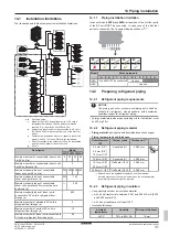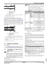
12 Special requirements for R32 units
Installation and operation manual
20
SV1ASV4~8A14AJV1B
VRV 5 safety valve unit
4P709466-1 – 2023.09
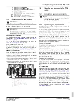
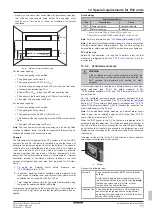
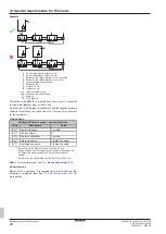
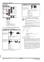
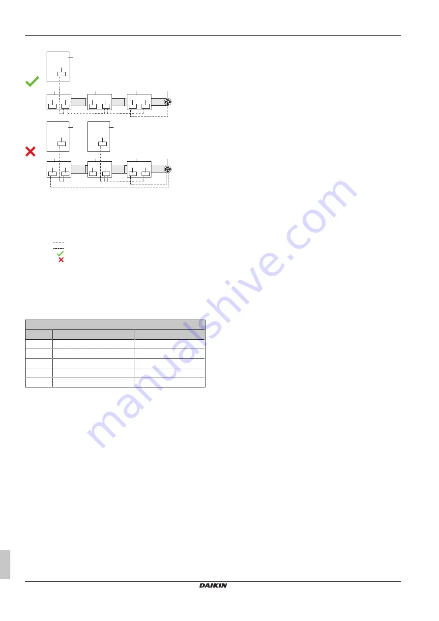
Example
a
a
a
f
c
e
c
e
d
e
A
e
a
b
b
f
d
e
c
e
d
e
A
e
B
e
a
SV unit belonging to outdoor unit A
b
SV unit belonging to outdoor unit B
c
Extraction fan output terminal – NOT connected
d
Extraction fan output terminal – connected
e
Interconnection wiring terminal
f
Extraction fan
A
Outdoor unit A
B
Outdoor unit B
Interconnection wiring
Extraction fan output wiring
Allowed
NOT allowed
The option kit EKBSDCK is required each time a duct is connected
to the air inlet (damper side) of the SV unit.
An online tool (
) is available to find the required pressure
capacity for selecting the correct fan size. Only use this online tool
for the calculation.
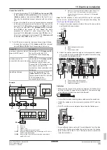
Field settings
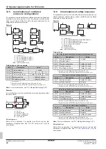
Multiple SV units in series – one extraction fan
Code
Description
Value
[2-0]
(a)
Cluster indication
1: enable
[2-1]
(a)
Cluster number
#
(b)
[2-2]
(a)
Cluster configuration
1: series
[2-4]
(c)
Safety measures
1 (default): enable
[2-7]
(c)
Ventilated enclosure
1 (default): enable
(a)
Set on ALL main PCBs (A1P and A2P) of the SV unit.
(b)
Assign a unique cluster number to each cluster in the system. All
SV units in the same cluster MUST have the same cluster
number.
(c)
Set ONLY on the LEFTMOST main PCB (A1P) of the SV unit.
Note:
For more information, see
SV unit test run
Before SV unit operation, it is required to perform a test run that
simulates a refrigerant leak. See
41] for
more details.


