15 Electrical installation
Installation and operation manual
36
SV1ASV4~8A14AJV1B
VRV 5 safety valve unit
4P709466-1 – 2023.09
a
b
c
a
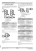
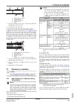
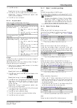
Spare cable
b
Switch box in upper position
c
Switch box in lower position
7
Reattach the service cover. See
25].
CAUTION
Be careful NOT to pinch cables between the service cover
and the switch box.
15.4
To finish the electrical wiring
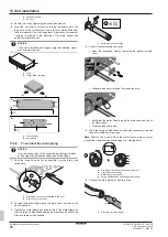
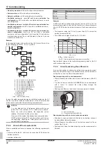
After installing the interconnection wiring, wrap it along with the
onsite refrigerant piping using finishing tape, as shown in the
illustration below.
b
d
a
c
e
a
Liquid piping
b
Gas piping
c
Finishing tape
d
Interconnection cable (F1/F2)
e
Insulation
15.5
To set the DIP switches
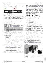
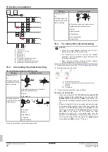
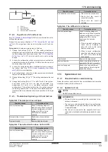
The DIP switches are located on the PCBs A1P, A2P (SV6~8A).
A1P
A2P
A B C D
E F G H
A B
C D
E F
G H
b
a
c
ON
DS1
OFF
1 2 3 4
ON
DS2
OFF
1 2 3 4
a
Terminal for interconnection wiring to indoor unit
b
Branch pipe port (A, B, C, …)
c
DIP switches
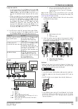
To set the DIP switches for branch pipe ports to which NO
indoor unit is connected
Setting for branch pipe ports to which NO indoor unit is
connected
(a)
DS1 (A1P)
DS1 (A2P)
1
2
3
4
1
2
3
4
SV1A
A
SV4A
B
C
D
SV6A
E
F
SV8A
G
H
Target branch pipe port
(a)
ON
=NOT connected /
OFF
=connected (factory default)
Note:
The SV1A unit requires no DIP switch setting. The factory
default setting can be used for any indoor unit connected to the
branch port.
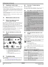
Example
When connecting an indoor unit to
branch pipe ports A and B, but NOT
connecting an indoor unit to branch pipe
ports C and D.
ON
DS1 (A1P)
OFF
1 2 3 4
To set the DIP switches when joining branch pipe ports
This is required for connection with e.g. FXMA200 and FXMA250.
Setting when joining branch pipe ports
(a)
DS2 (A1P)
DS2 (A2P)
1
2
1
2
SV1A
SV4A
A+B
C+D
SV6A
E+F
SV8A
G+H
Target branch pipe ports
(a)
ON
=joined /
OFF
=NOT joined (factory default)
Note:
When joining branch pipe ports, ONLY the combinations in
above table are possible. E.g.: it is NOT possible to join ports B and
C.
Example
When joining branch pipe ports A and B.
ON
DS2 (A1P)
OFF
1 2 3 4
Examples
1.
When connecting an indoor unit to branch pipe
ports A, B, and D, but NOT connecting an indoor
unit to branch pipe port C.
ON
DS1 (A1P)
OFF
1 2 3 4
ON
DS2 (A1P)
OFF
1 2 3 4
2.
When joining branch pipe ports A and B.
Connecting an indoor unit to the joined branch
pipe ports A and B, also to branch pipe port C, but
NOT connecting an indoor unit to branch pipe
port D.
ON
DS1 (A1P)
OFF
1 2 3 4
ON
DS2 (A1P)
OFF
1 2 3 4
15.6
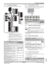
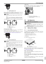
To connect the external outputs
FAN output (extraction fan)
The extraction FAN output is a contact on terminal X6M that closes
in case a leak is detected, or when there is a failure or disconnection
of the R32 sensor in the SV unit.
The FAN output must be used when a ventilated enclosure is
required
(see

