background image

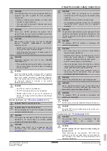
2 Specific installer safety instructions

Installation and operation manual

5

SV1ASV4~8A14AJV1B
VRV 5 safety valve unit
4P709466-1 – 2023.09

WARNING

Take sufficient precautions in case of refrigerant leakage. If
refrigerant  gas  leaks,  ventilate  the  area  immediately.
Possible risks:

▪ Excessive  refrigerant  concentrations  in  a  closed  room

can lead to oxygen deficiency.

▪ Toxic  gas  might  be  produced  if  refrigerant  gas  comes

into contact with fire.

WARNING

During  tests,  NEVER  pressurise  the  product  with  a
pressure higher than the maximum allowable pressure (as
indicated on the nameplate of the unit).

WARNING

Bent  header  or  branch  pipes  can  lead  to  refrigerant
leakage. 

Possible 

consequence: 

asphyxiation,

suffocation and fire.

▪ NEVER bend the branch and header pipes sticking out

of the unit. They have to remain straight.

▪ ALWAYS  support  the  branch  and  header  pipes  at  a

distance of 1 m from the unit.

WARNING

Overheated  insulation  can  start  to  burn. 

Possible

consequence: 

fire.

▪ When performing brazing work header or branch pipes,

cool  all  other  header  and  branch  pipes  by  wrapping
them in wet cloths.

CAUTION

Install  the  refrigerant  piping  or  components  in  a  position
where  they  are  unlikely  to  be  exposed  to  any  substance
which  may  corrode  components  containing  refrigerant,
unless  the  components  are  constructed  of  materials  that
are  inherently  resistant  to  corrosion  or  are  suitably
protected against corrosion.

CAUTION

▪ Do NOT use mineral oil on flared part.

▪ Do NOT reuse piping from previous installations.

▪ NEVER  install  a  drier  to  this  unit  to  guarantee  its

lifetime. The drying material may dissolve and damage
the system.

Electrical installation (see 

"15 Electrical installation"

 [

4

 33])

DANGER: RISK OF ELECTROCUTION

DANGER: RISK OF ELECTROCUTION

Before performing work on the unit, disconnect any power
source connected to the unit.

WARNING

If the supply cord is damaged, it MUST be replaced by the
manufacturer,  its  service  agent  or  similarly  qualified
persons in order to avoid a hazard.

WARNING

Electrical  wiring  MUST  be  in  accordance  with  the
instructions  from  this  manual.  See 

"15  Electrical

installation"

 [

4

 33].

WARNING

▪ All  wiring  MUST  be  performed  by  an  authorised

electrician  and  MUST  comply  with  the  national  wiring
regulation.

▪ Make electrical connections to the fixed wiring.

▪ All  components  procured  on-site  and  all  electrical

construction  MUST  comply  with  the  applicable
legislation.

WARNING

The electrical components shall only be replaced with parts
specified by the appliance manufacturer. Replacement with
other  parts  may  result  in  the  ignition  of  refrigerant  in  the
event of a leak.

WARNING

The  appliance  MUST  be  installed  in  accordance  with
national wiring regulations.

WARNING

▪ If  the  power  supply  has  a  missing  or  wrong  N-phase,

equipment might break down.

▪ Establish  proper  earthing.  Do  NOT  earth  the  unit  to  a

utility  pipe,  surge  absorber,  or  telephone  earth.
Incomplete earthing may cause electrical shocks.

▪ Install the required fuses or circuit breakers.

▪ Secure  the  electrical  wiring  with  cable  ties  so  that  the

cables do NOT come into contact with sharp edges or
piping, particularly on the high-pressure side.

▪ Do  NOT  use  taped  wires,  extension  cords,  or

connections  from  a  star  system.  They  can  cause
overheating, electrical shocks or fire.

WARNING

ALWAYS use multicore cable for power supply cables.

WARNING

Use  an  all-pole  disconnection  type  breaker  with  at  least
3  mm  between  the  contact  point  gaps  that  provides  full
disconnection under overvoltage category III.

WARNING

The  appliance  MUST  be  installed  in  accordance  with
national wiring regulations.

CAUTION

Do NOT push or place redundant cable length into the unit.

CAUTION

Be careful NOT to pinch cables between the service cover
and the switch box.

Commissioning (see 

"17 Commissioning"

 [

4

 41])

WARNING

Commissioning  MUST  be  in  accordance  with  the
instructions 

from 

this 

manual. 

See

"17 Commissioning"

 [

4

 41].

CAUTION

Do  NOT  perform  the  test  operation  while  working  on
the indoor units.

When  performing  the  test  operation,  NOT  ONLY  the
outdoor unit, but the connected indoor unit will operate as
well.  Working  on  an  indoor  unit  while  performing  a  test
operation is dangerous.

Содержание VRV 5

Страница 1: ...Installation and operation manual VRV 5 safety valve unit English Installation and operation manual VRV 5 safety valve unit SV1A25AJV1B SV4A14AJV1B SV6A14AJV1B SV8A14AJV1B...

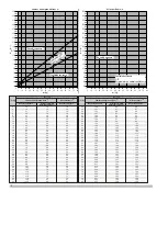
Страница 2: ...larm OR Natural Ventilation d 5 15 10 10 43 128 85 85 6 18 12 12 131 87 87 7 21 14 14 44 134 89 89 8 24 16 16 45 137 91 91 9 27 18 18 46 140 93 93 10 30 20 20 47 143 95 95 11 33 22 22 48 146 97 97 12...

Страница 3: ...all the drain piping 27 13 5 Installing the ventilation ducting 27 13 5 1 To install the ducting 27 13 5 2 To install the duct closing plate 27 13 5 3 To switch the air in and outlet side 28 14 Piping...

Страница 4: ...with the instructions from this manual See 13 4 Mounting the unit 425 WARNING Follow the service space dimensions in this manual to install the unit correctly See 13 1 1 Installation site requirement...

Страница 5: ...order to avoid a hazard WARNING Electrical wiring MUST be in accordance with the instructions from this manual See 15 Electrical installation 433 WARNING All wiring MUST be performed by an authorised...

Страница 6: ...iance shall be stored as follows in such a way as to prevent mechanical damage in a well ventilated room without continuously operating ignition sources example open flames an operating gas appliance...

Страница 7: ...e the system yourself dismantling the system treatment of the refrigerant of oil and of other parts MUST be done by an authorised installer and MUST comply with applicable legislation Units MUST be tr...

Страница 8: ...lace a fuse with a fuse of a wrong ampere ratings or other wires when a fuse blows out Use of wire or copper wire may cause the unit to break down or cause a fire WARNING If the supply cord is damaged...

Страница 9: ...mentation set and in addition comply with applicable legislation and are performed by qualified persons only In Europe and areas where IEC standards apply EN IEC 60335 2 40 is the applicable standard...

Страница 10: ...performing maintenance at least once a year However applicable legislation might require shorter maintenance intervals Following symbols may occur on the indoor unit Symbol Explanation Measure the vol...

Страница 11: ...f a refrigerant leak occurs error code Actions will be taken by the system Do NOT turn OFF the power supply Contact your installer and report the error code If a safety device such as a fuse a breaker...

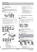
Страница 12: ...be for stopper pipe 15 9 mm 4 for SV4A 2 for SV1A and SV6 8A k Insulation tube for stopper pipe 22 2 mm l Cable ties 8 for SV4A 11 for SV1A and SV6 8A m Duct closing plate n Stopper pipe 9 5 mm 2 for...

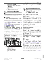
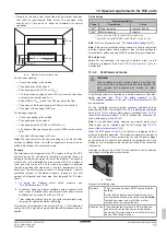
Страница 13: ...tion to a minimum 12 2 System layout requirements The VRV 5 heat pump uses R32 refrigerant which is rated as A2L and is mildly flammable To comply with the requirements of enhanced tightness refrigera...

Страница 14: ...required it is still allowed to install an external alarm or ventilated enclosure if wanted Follow the respective instructions as described further below Note When an external alarm is required as sa...

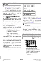
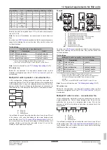
Страница 15: ...3 in above text See Step3 in above text Determine required safety measure based on Lowest underground floor of the graph and table Determine required safety measure based on All other floors of the gr...

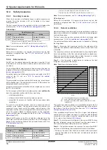
Страница 16: ...Safety measures 1 default enable 2 7 b Ventilated enclosure 0 disable a Set on ALL main PCBs A1P and A2P of the SV unit b Set ONLY on the LEFTMOST main PCB A1P of the SV unit Note For more information...

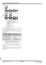
Страница 17: ...asure can be applied Field settings Natural ventilation Code Description Value 2 0 a Cluster indication 0 default disable 2 4 b Safety measures 0 disable a Set on ALL main PCBs A1P and A2P of the SV u...

Страница 18: ...he components in the evacuation channel for the selected airflow rate For the SV unit use the curve that presents the pressure at the outlet POUT in function of the airflow rate AFROUT See the latest...

Страница 19: ...6 If in a cluster there are SV units that belong to different outdoor unit systems the fan circuit must be connected to one SV unit in the cluster of each outdoor unit system Example a a a A c e c e d...

Страница 20: ...press is available to find the required pressure capacity for selecting the correct fan size Only use this online tool for the calculation Field settings Multiple SV units in series one extraction fan...

Страница 21: ...a supervised location with 24 hour monitoring Pressure inside the SV unit Pinternal must be 20 Pa below the pressure of the surroundings Select a fan with the selected airflow and calculated pressure...

Страница 22: ...tural ventilation and ventilated enclosure in the same system Example a b b f g d c e h a Outdoor unit b SV unit with ventilated enclosure safety measure c SV unit without safety measures d SV unit wi...

Страница 23: ...pect the following conditions Ambient condition Value Indoor temperature 5 32 C DB Indoor humidity 80 Do NOT install the unit in the following places In places where a mineral oil mist spray or vapour...

Страница 24: ...is strong enough to support the weight of the unit If there is a risk reinforce the ceiling before installing the unit For existing ceilings use anchors For new ceilings use sunken inserts sunken anch...

Страница 25: ...nit DANGER RISK OF ELECTROCUTION Do NOT leave the unit unattended when the service cover is removed 13 3 2 To open the unit DANGER RISK OF ELECTROCUTION Do NOT leave the unit unattended when the servi...

Страница 26: ...in pipe connection 1 a b a Drain pipe connection attached to the unit b Drain hose accessory 2 Position the metal clamp around the drain hose as close to the unit as possible 3 Tighten the metal clamp...

Страница 27: ...onnections in the system do not leak air 3 Insulate the ducting with field supply thermal insulation and with the accessory sealing material against condensation drops Insulate at least the first mete...

Страница 28: ...2 Loosen the damper wires in the switch box Cut the cable tie that fixes the connector Unplug the damper wire from the connector Loosen and remove the damper earth wire screw and detach the damper ea...

Страница 29: ...l hole in the unit s metal plate This makes the connection airtight Attach the damper with four screws a b b b b c 2 4 PH2 SW8 3 2 N m 1 a Damper wire b Screw c Damper 2 Connect the damper wires in th...

Страница 30: ...ch box Bundle the damper wire if needed SV1A b a b b b SV4A b a b b b SV6A b b a SV8A b b a a Damper wire b Cable tie to fix damper wire to piping field supply c Cable tie to bundle the damper wire fi...

Страница 31: ...in refrigerant flow through c 16 Maximum number of indoor units connected to SV units in refrigerant flow through c 64 14 1 1 Piping installation limitation In case of models SV6A and SV8A at least o...

Страница 32: ...on c d b a 6 35mm 9 5mm 12 7mm 15 9mm 9 5mm a Liquid branch pipe b Gas branch pipe c Liquid header pipe d Gas header pipe 3 Connect the branch pipes The liquid and gas branch pipe diameters to be used...

Страница 33: ...ng including earth DIII interconnection wiring between units NOTICE Keep the power line and transmission line apart from each other Transmission wiring and power supply wiring may cross but may NOT ru...

Страница 34: ...the electrical wiring NOTICE Follow the wiring diagram delivered with the unit located at the inside of the service cover For instructions on how to connect the optional equipment see the installation...

Страница 35: ...V UNIT F1 F2 F1 F2 F1 F2 F1 F2 F1 F2 F1 F2 TO IN D TO OUT D F1 F2 F1 F2 F1 F2 F1 F2 F1 F2 F1 F2 F1 F2 INDOOR UNIT A INDOOR UNIT B INDOOR UNIT C INDOOR UNIT D OUT DOOR UNIT SV UNIT F1 F2 F1 F2 F1 F2 F1...

Страница 36: ...ting can be used for any indoor unit connected to the branch port Example When connecting an indoor unit to branch pipe ports A and B but NOT connecting an indoor unit to branch pipe ports C and D ON...

Страница 37: ...MPLE a SVS output terminal b Relay power supply c Relay d External alarm power supply e External alarm Cable routing Route the FAN or SVS output cable as indicated below Leave 20 cm additional length...

Страница 38: ...s is established and normal the 7 segment display indication state will be as below default situation when shipped from factory Stage Display Ready for operation blank display indication as indicated...

Страница 39: ...ration according to the chosen setting 8 Push BS1 one time to quit mode 2 16 1 7 Mode 1 monitoring settings 1 0 Shows the remaining lifetime of the R32 sensor The remaining lifetime is displayed in mo...

Страница 40: ...ain PCB A1P of the SV unit 2 8 Setting to assign an address value to the SV unit for the supervisor remote controller In case supervisor remote controllers are used in the system it is necessary to as...

Страница 41: ...the complete installation and operation instructions described in the installer and user reference guide The SV unit is properly mounted The field wiring has been carried out according to the instruct...

Страница 42: ...ose If any part of the system had already been powered before FIRST activate setting 2 21 on the outdoor unit to open the expansion valves again THEN power off the unit to conduct the SV unit test run...

Страница 43: ...Check if all field settings are made correctly When in parallel or series configuration the field settings of all SV units in a cluster need to be made correctly Damper wiring is loose Reattach any lo...

Страница 44: ...complies with all safety regulations 20 1 Overview Troubleshooting Before troubleshooting Carry out a thorough visual inspection of the unit and look for obvious defects such as loose connections or d...

Страница 45: ...Outdoor unit Wire clamp Residual current device Symbol Colour Symbol Colour BLK Black ORG Orange BLU Blue PNK Pink BRN Brown PRP PPL Purple GRN Green RED Red GRY Grey WHT White YLW Yellow Symbol Mean...

Страница 46: ...2 3 4 Model DS1 DS2 factory settings SV4A ON DS1 A1P OFF 1 2 3 4 ON DS2 OFF 1 2 3 4 SV6A ON DS1 A1P OFF 1 2 3 4 ON DS2 OFF 1 2 3 4 ON DS1 A2P OFF 1 2 3 4 ON DS2 OFF 1 2 3 4 SV8A ON DS1 A1P OFF 1 2 3...

Страница 47: ......

Страница 48: ...4P709466 1 2023 09 Copyright 2023 Daikin 4P709466 1 0000000U Verantwortung f r Energie und Umwelt...

Отзывы: