


www.DaikinApplied.com
9
AG 31-011 • REFRIGERANT PIPING DESIGN
Piping Design Basics
Good piping design results in a balance between the initial
cost, pressure drop, and system reliability. The initial cost
is impacted by the diameter and layout of the piping.The
pressure drop in the piping must be minimized to avoid
adversely affecting performance and capacity. Because almost
all field-piped systems have compressor oil passing through
the refrigeration circuit and back to the compressor, a minimum
velocity must be maintained in the piping so that sufficient
oil is returned to the compressor sump at full and part load
conditions. A good rule of thumb is a minimum of:
• 500 feet per minute (fpm) or 2.54 meters per second
(mps) for horizontal suction and hot gas lines
• 1000 fpm (5.08 mps) for suction and hot gas risers
• Less than 300 fpm (1.54 mps) to avoid liquid hammering
from occurring when the solenoid closes on liquid lines
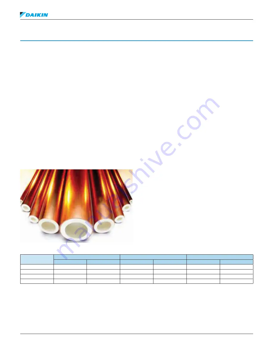
Hard drawn copper tubing is used for halocarbon refrigeration
systems. Types L and K are approved for air conditioning and
refrigeration (ACR) applications. Type M is not used because
the wall is too thin. The nominal size is based on the outside
diameter (OD). Typical sizes include 5/8 inch, 7/8 inch, 1-1/8
inch, etc.
Figure 5: Refrigerant Grade Copper Tubing
Copper tubing intended for ACR applications is dehydrated,
charged with nitrogen, and plugged by the manufacturer (see
).
Formed fittings, such as elbows and tees, are used with the
hard drawn copper tubing. All joints are brazed with oxy-
acetylene torches by a qualified technician.
As mentioned before, refrigerant line sizes are selected to
balance pressure drop with initial cost, in this case of the
copper tubing while also maintaining enough refrigerant
velocity to carry oil back to the compressor.
Pressure drops are calculated by adding the length of tubing
required to the equivalent feet (meters) of all fittings in the line.
This is then converted to PSI (kPa).
Pressure Drop and Temperature Change
As refrigerant flows through pipes the pressure drops and
changes the refrigerant saturation temperature. Decreases
in both pressure and saturation temperature adversely affect
compressor performance. Proper refrigeration system design
attempts to minimize this change to less than 2°F (1.1°C) per
line. Therefore, it is common to hear pressure drop referred to
as “2°F” versus PSI (kPa) when matching refrigeration system
components. For example, a condensing unit may produce
25 tons (87.9 kW) of cooling at 45°F (7.2°C) saturated suction
temperature. Assuming a 2°F (1.1°C) line loss, the evaporator
would have to be sized to deliver 25 tons (87.9 kW) cooling at
47°F (7.2°C) saturated suction temperature.
compares pressure drops in temperatures and
pressures for several common refrigerants. Note that the
refrigerants have different pressure drops for the same
change in temperature. For example, many documents refer
to acceptable pressure drop being 2°F (1.1°C) or about 3 PSI
(20.7 kPa) for R-22. The same 3 PSI change in R-410A, results
in a 1.2°F (0.7°C) change in temperature.
Table 1: Temperature versus Pressure Drop
Refrigerant
Suction Pressure Drop
Discharge Pressure Drop
Liquid Pressure Drop
°F (°C)
PSI (kPa)
°F (°C)
PSI (kPa
°F (°C)
PSI (kPa)
R-22
2 (1.1)
2.91 (20.1)
1 (0.56)
3.05 (21.0)
1 (0.56)
3.05 (21.0)
R-407C
2 (1.1)
2.92 (20.1)
1 (0.56)
3.3 (22.8)
1 (0.56)
3.5 (24.1)
R-410A
2 (1.1)
4.5 (31.0)
1 (0.56)
4.75 (32.8)
1 (0.56)
4.75 (32.8)
R-134a
2 (1.1)
1.93 (13.3)
1 (0.56)
2.2 (15.2)
1 (0.56)
2.2 (15.2)
NOTE:
Suction and discharge pressure drops based on 100 equivalent feet (30.5 m) and 40°F (4.4°C) saturated temperature.