


AG 31-011 • REFRIGERANT PIPING DESIGN 28 www.DaikinApplied.com
Thermal Expansion Valves
Expansion valves are used to modulate refrigerant flow to
the evaporator. There are several types of expansion valves
including:
•
Fixed area restrictor (capillary and orifice types)
• Automatic (constant pressure)
• Thermal expansion (TX)
• Electronic
For field-piped systems, the TX and electronic types are
commonly used. Electronic valves require significant controls
to operate and normally are used if they were included as part
of the original equipment.
Figure 16: Thermal Expansion Valve
Photo courtesy of Sporlan Division – Parker Hannifin Corporation
) are excellent for DX systems because
they modulate refrigerant flow and maintain constant superheat
at the evaporator. As superheat climbs, the TX valve opens
allowing more refrigerant to flow. As superheat drops, the valve
closes to maintain superheat.
TX valves are sized by:
• Refrigerant type
• Refrigeration circuit capacity
• Pressure drop across the valve
• Equalization (internal or external)
For smaller systems, an internally equalized TX valve is
acceptable. For larger systems (greater than 2 PSI [13.8kPa]
pressure drop across the evaporator, or if a distributor is used)
an externally equalized TX valve is recommended. An external
line accounts for the pressure drop through the evaporator
which becomes an issue on larger evaporator coils.
TX valves and distributors (common with air coils) should
be installed in vertical pipes. If a TX valve with a distributor
is installed in a horizontal pipe, there is a possibility that the
liquid portion of the two-phase flow downstream of the TX
valve will fill the distributor tubes on the bottom, leading to
different refrigerant flow rates in the individual tubes. This is
not an issue with nozzles (common with chillers), so horizontal
installations are acceptable.
TX valves should be sized as close to capacity as possible.
Use of nominal TX valve capacity is discouraged. Follow the
manufacturer’s selection procedures and select the valve
for the actual operating conditions. Under-sizing up to 10%
is acceptable if there will be significant part load operation.
Higher superheat conditions at full load are allowable.
There must be one TX valve for each distributor. For large DX
field applications there are often multiple refrigeration circuits,
each with its own compressor, evaporator circuit, and TX valve.
Evaporator circuits may be in a common evaporator coil such
as interlaced, face split, or row split type (For more information
about evaporator circuits see
“Multiple Refrigeration Circuits”
. On occasions where there are multiple
evaporators on a common refrigeration circuit, separate TX
valves and solenoid valves are required for each evaporator.
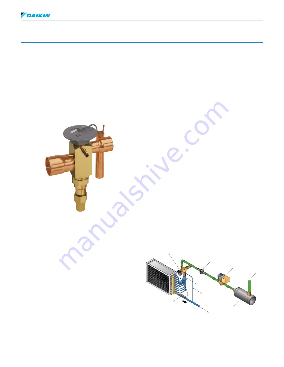
shows a typical TX valve installation.
1.
The sensing bulb is strapped to the suction line on the
top (12 o’clock) for line sizes under 7/8 inch (22 mm) and
at 4 or 8 o’clock for larger line sizes. The bulb should be
tightly strapped to a straight portion of the suction line
and insulated unless it is in the leaving airstream.
2.
The equalization line should be downstream of the
bulb. Refer to manufacturer’s installation instructions for
specific details.
3.
Neither the bulb nor the equalization line should be
installed in a trap.
Figure 17: Typical TX Valve Installation
TX valve
in vertical pipe
Sight
Glass
Solenoid
Valve
Liquid
Line
Filter-
Drier
Distributor
External
Equalization
Line
Suction
Line
Bulb