AG 31-011
Refrigerant Piping Design Guide
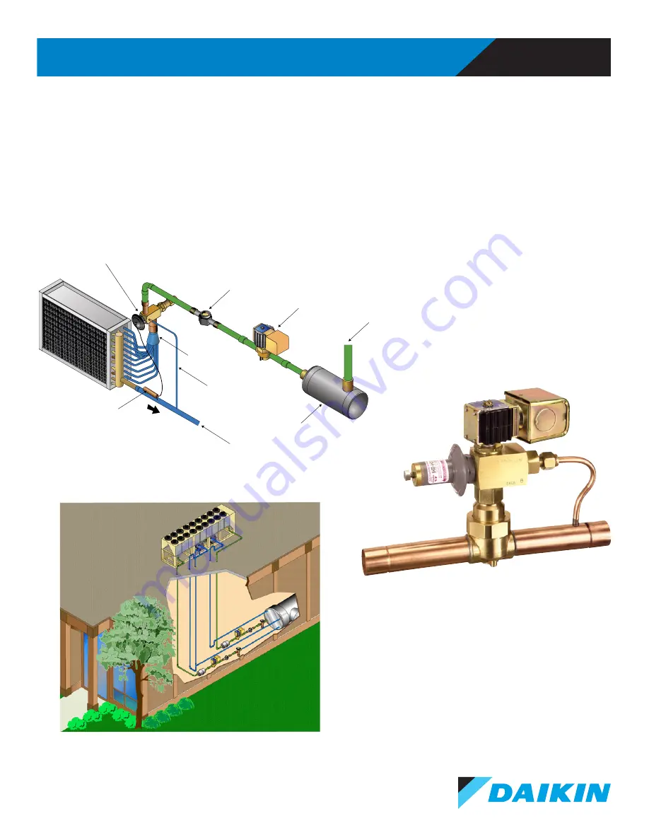
TX valve
in vertical pipe
Sight
Glass
Solenoid
Valve
Liquid
Line
Filter-
Drier
Distributor
External
Equalization
Suction
Bulb
Страница 1: ...AG 31 011 Refrigerant Piping Design Guide TX valve in vertical pipe Sight Glass Solenoid Valve Liquid Line Filter Drier Distributor External Equalization Line Suction Line Bulb...
Страница 2: ...ction Lines 11 Suction Line Piping Details 11 Discharge Lines 13 Discharge Line Piping Details 14 Multiple Refrigeration Circuits 15 Sizing Refrigerant Lines 16 Refrigerant Capacity Tables 16 Equivale...
Страница 3: ...appear under shaded headlines as seen below How to Determine Equivalent Length Calculate the equivalent length of the liquid line for the following condensing unit with DX air handling unit The liquid...
Страница 4: ...he information contained in this Application Guide is based on Chapter 2 of ASHRAE s Refrigeration Handbook and Daikin Applied s experience with this type of equipment A properly designed and installe...
Страница 5: ...eration circuit Unit operating charge Unit pump down capacity Refrigerant type Unit options Hot Gas Bypass etc Does equipment include isolation valves and charging ports Does the unit have pump down J...
Страница 6: ...ed on grade connected to a DX coilinstalled in a roof mounted air handling unit 1 A liquid line supplies liquid refrigerant from the condenser to a thermal expansion TX valve adjacent to the coil 2 A...
Страница 7: ...d a suction line returning refrigerant gas from the evaporator to the suction connections of the compressor 2 There is a double suction riser on one of the circuits Double suction risers are covered i...
Страница 8: ...to a TX valve at the evaporator 3 The hot gas bypass line on the circuit runs from the discharge line of the compressor to the liquid line connection at the evaporator Figure 4 Indoor Chiller with Re...
Страница 9: ...e of the copper tubing while also maintaining enough refrigerant velocity to carry oil back to the compressor Pressure drops are calculated by adding the length of tubing required to the equivalent fe...
Страница 10: ...alled above the evaporator the pressure increase from the weight of the liquid refrigerant in the line would have prevented the refrigerant from flashing in a properly sized line without sub cooling I...
Страница 11: ...ping Details While operating the suction line is filled with superheated refrigerant vapor and oil The oil flows on the bottom of the pipe and is moved along by the refrigerant gas flowing above it Wh...
Страница 12: ...Slope in direction of the refrigerant flow Slope in direction of refrigerant flow Trap to protect TX valve bulb from liquid refrigerant Compressor Above Coil Slope in direction of refrigerant flow Tr...
Страница 13: ...erant Figure 9 illustrates how capacity and power consumption are affected by increasing pressure drop for both discharge and suction lines Although these curves are based on an R 22 system similar af...
Страница 14: ...should be pitched 1 8 inch per foot 10 4 mm m in the direction of refrigerant flow towards the condenser Figure 10 Whenever a condenser is located above the compressor an inverted trap or check valve...
Страница 15: ...evaporators to a single refrigeration circuit Figure 12 shows a single refrigeration circuit serving two DX coils Note that each coil has its own solenoid and thermal expansion valve There should be o...
Страница 16: ...ensing temperature common for water cooled equipment and must be corrected for other condensing temperatures air cooled equipment is typically 120 to 125 F 48 9 to 51 7 C The tables are also based on...
Страница 17: ...m long radius elbow has a pressure drop equivalent to 1 4 feet 0 43 m of straight copper pipe How to Determine Equivalent Length Calculate the equivalent length of the liquid line for the following co...
Страница 18: ...mperature at the TX Valve Referring back to the Refrigeration property tables in Application Guide 31 007 the saturation temperature at the TX valve can be interpolated using the saturation pressure a...
Страница 19: ...bcooling 120 0 F 117 8 F 2 2 F Step 8 Determine the Required Sub cooling for Proper Operation 2 2 F is the amount of sub cooling required to have saturated liquid refrigerant at the TX valve Anything...
Страница 20: ...long liquid lines Residential split systems are often pre charged at the factory with enough oil and refrigerant for a specified line distance When that distance is exceeded additional refrigerant and...
Страница 21: ...e drop at full capacity for optimal oil movement To compensate a larger diameter pipe may be used for horizontal runs to minimize the total pressure drop Figure 13 shows the traditional method for red...
Страница 22: ...s through the smaller diameter riser The sum of the two risers is sized for full capacity The smaller diameter riser is sized for minimum capacity One of the challenges of double suction risers is tha...
Страница 23: ...ctual design conditions Step 4 Calculate the Actual Pressure Drop The top of Table 8 shows the pressure drop for 40 F 4 4oC saturation temperature change with a 100 ft 30 5m equivalent length is 1 93...
Страница 24: ...9 PSI Pressure DropTotal 12 21 kPa 2 78 kPa 14 99 kPa TActual 2 F TActual 1 1 C 0 42 F 22 0 ft 100 0 ft 50 0 Tons 51 5 Tons 1 8 0 23 C 6 7 m 30 5 m 176 kW 181 kW 1 8 TActual TTable Actual Length Table...
Страница 25: ...table conditions equivalent length and condensing temperature are different than the design conditions Step 3 Correct for Actual Operating Conditions Sizing the pipe for full load requires a correcti...
Страница 26: ...kW unit use Table 7 on page 42 in Appendix 2 According to the table a 4 1 8 inch 105 mm pipe will work for a 276 1 ton 970 kW unit with 20 F 6 7 C Saturated Suction Temperature Note the table conditio...
Страница 27: ...e are given as 140 F and 110 F respectively The actual SST and superheat are given as 20 F and 15 F respectively Using Table 15 on page 48 with the above given conditions the minimum allowable capacit...
Страница 28: ...valve will fill the distributor tubes on the bottom leading to different refrigerant flow rates in the individual tubes This is not an issue with nozzles common with chillers so horizontal installati...
Страница 29: ...utor may need a different nozzle On DX coils that have a venturi a standard copper tee fitting may be used to introduce the hot gas Hot gas bypass lines include a solenoid valve and a hot gas bypass v...
Страница 30: ...pressure Over sizing the HGBP valve may cause System inversion Loss of oil management Prevent the compressor from cycling OFF overheating Poor efficiency Hot gas valve selection is based on Refrigeran...
Страница 31: ...1 0 13 9 8 24 10 6 13 5 ADRHE 6 0 30 10 8 13 9 17 6 10 9 14 1 17 8 10 5 13 5 17 1 0 80 7 12 9 16 11 5 7 69 9 90 12 5 7 92 10 2 12 8 8 44 10 9 13 7 8 55 11 0 13 9 8 24 10 6 13 5 134a ADRI 1 1 4 ADRIE 1...
Страница 32: ...0 787 11 65 kW Step 4 Calculate the Actual T Using Note 5 in the table we can calculate the saturation temperature difference based upon the actual design conditions Step 5 Calculate the Actual Pressu...
Страница 33: ...igerant Consult the manufacturer if a receiver is required Piping Insulation Suction lines are cold 40 F 4 4 C SST and cause condensation even in conditioned spaces In addition any heat that enters th...
Страница 34: ...ng a port for the head pressure sensor Condenser Flood Back Design Figure 20 shows a typical condenser flood back arrangement As the ambient temperature drops the head pressure drops A head pressure c...
Страница 35: ...www DaikinApplied com 35 AG 31 011 REFRIGERANT PIPING DESIGN Figure 20 Typical Condenser Flood Back Arrangement Head Pressure Control Valve Discharge Line Liquid Line Receiver Condenser Coil...
Страница 36: ...and pressures Proper safety procedures must be followed to provide a system that is acceptable ASHRAE Standard 15 Safety Code for Mechanical Refrigeration and ASME Standard B31 5 Refrigeration Piping...
Страница 37: ...ch tube of a DX evaporator It is usually part of the coil and is directly down stream of the TX valve Economizer Refrigerant A form of two stage refrigeration cycle where the compressor has a port tha...
Страница 38: ...r load Examples include fan cycling fan speed control and liquid flood back control Mass m The quantity of a substance present It is measured in pounds or lbm or kilograms kg Oil Separator A vessel in...
Страница 39: ...e liquid refrigerant pressure from the condensing pressure to the evaporation pressure Thermal expansion valves modulate refrigerant flow based on superheat in the suction line Trap A P shaped piping...
Страница 40: ...1 257 0 884 365 684 1 5 8 K 0 072 1 625 1 481 0 425 0 388 0 351 1 723 1 361 404 758 L 0 060 1 625 1 505 0 425 0 394 0 295 1 779 1 143 337 631 2 1 8 K 0 083 2 125 1 959 0 556 0 513 0 532 3 014 2 063 3...
Страница 41: ...0 8 2 21 0 6 5 11 0 21 0 25 0 8 2 12 0 13 0 6 1 8 16 0 10 0 25 0 7 9 13 0 25 0 30 0 10 0 14 0 16 0 8 1 8 20 0 13 0 10 0 33 0 40 0 13 0 18 0 20 0 ASHRAE Handbook Refrigeration Chapter 2 2006 American S...
Страница 42: ...95 68 66 09 190 3 196 2 202 1 147 8 895 7 4 1 8 92 2 63 71 43 85 136 3 94 25 65 12 194 3 134 81 93 22 267 8 276 1 284 4 192 1 1263 2 ASHRAE Handbook Refrigeration Chapter 2 2006 American Society of H...
Страница 43: ...3 37 4 119 4 82 6 57 1 181 0 191 200 0 175 971 5 1 8 88 90 61 3 42 2 141 0 97 2 67 1 213 0 148 102 323 0 340 356 0 6 1 8 143 0 98 8 68 0 226 0 157 108 342 0 237 165 518 0 545 571 0 ASHRAE Handbook Ref...
Страница 44: ...04 8 142 1 413 8 426 1 435 9 165 7 1530 2 3500 9 5 1 8 253 1 175 4 121 5 370 8 258 0 179 2 523 2 365 0 253 8 737 3 759 3 776 7 258 2 2729 8 6228 4 6 1 8 405 8 282 3 195 7 594 9 414 5 287 8 839 8 586 1...
Страница 45: ...72 6 284 0 295 0 171 8 1281 5 2923 4 5 1 8 141 6 97 9 67 6 218 1 151 2 104 7 323 5 225 1 156 1 485 5 505 8 525 3 267 8 2288 8 5209 1 6 1 8 227 9 157 6 109 0 350 4 243 2 168 4 519 6 361 7 251 1 779 0 8...
Страница 46: ...ing factors for other liquid line temperatures Liquid Temperature F 50 60 70 80 100 110 120 130 140 1 17 1 14 1 10 1 06 0 98 0 94 0 89 0 85 0 80 Table 12 R 134a Minimum Capacity for Suction Riser Tons...
Страница 47: ...page 2 17 of ASHRAE Handbook Refrigeration 2006 Liquid Temperature F 80 90 100 110 120 130 140 1 05 1 00 0 94 0 90 0 83 0 77 0 72 Table 14 R 407C Minimum Capacity for Suction Riser Tons Saturated Suc...
Страница 48: ...ondensing temperature with 15 F sub cooling For other saturated suction temperatures with 15 F superheat use correction factors in the following table Saturated Suction Temperature F 40 20 0 40 0 92 0...
Страница 49: ...tors in the following table Table data based on line size pressure drop formula shown on page 2 17 of ASHRAE Handbook Refrigeration 2006 Saturated Suction Temperature F 0 20 40 60 0 90 0 94 1 00 1 06...
Страница 50: ...ased on 105 F condensing temperature and 10 F sub cooling 140 F discharge temperature and 40 F saturated suction temperature Table 21 R 410A Refrigerant Charge Lbs per 100 feet of Pipe Line Size OD Fl...
Страница 51: ...4 0 76 90 1 67 1 51 1 37 1 24 1 13 1 02 0 93 0 85 0 78 95 1 71 1 54 1 40 1 27 1 15 1 05 0 95 0 87 0 80 100 1 75 1 58 1 43 1 30 1 18 1 07 0 98 0 89 0 82 105 1 79 1 62 1 46 1 33 1 20 1 10 1 00 0 91 0 83...
Страница 52: ...82 0 74 90 1 81 1 61 1 43 1 28 1 15 1 03 0 93 0 84 0 76 95 1 86 1 65 1 47 1 32 1 18 1 06 0 95 0 86 0 77 100 1 91 1 70 1 52 1 35 1 21 1 09 0 98 0 88 0 80 105 1 97 1 75 1 56 1 39 1 25 1 12 1 00 0 91 0...
Страница 53: ...82 0 75 90 1 64 1 48 1 34 1 22 1 11 1 01 0 92 0 84 0 77 95 1 69 1 53 1 38 1 25 1 14 1 04 0 95 0 86 0 79 100 1 74 1 57 1 42 1 29 1 17 1 07 0 97 0 89 0 81 105 1 79 1 62 1 46 1 33 1 21 1 10 1 00 0 91 0...
Страница 54: ...82 0 75 90 1 82 1 53 1 38 1 24 1 12 1 02 0 92 0 84 0 76 95 1 75 1 57 1 42 1 28 1 15 1 04 0 95 0 86 0 78 100 1 80 1 62 1 46 1 31 1 19 1 07 0 97 0 88 0 80 105 1 86 1 78 1 50 1 35 1 22 1 10 1 00 0 91 0...
Страница 55: ...37 1 39 1 42 90 1 12 1 15 1 17 1 20 1 23 1 26 1 28 1 31 1 33 95 1 05 1 08 1 10 1 13 1 16 1 18 1 21 1 23 1 26 100 0 98 1 01 1 04 1 06 1 09 1 11 1 14 1 16 1 19 105 0 92 0 95 0 97 1 00 1 03 1 05 1 07 1...
Страница 56: ...1 40 1 43 1 46 90 1 15 1 17 1 20 1 23 1 26 1 28 1 31 1 34 1 36 95 1 07 1 09 1 12 1 14 1 17 1 19 1 22 1 25 1 27 100 0 99 1 02 1 04 1 07 1 09 1 12 1 14 1 17 1 19 105 0 92 0 95 0 97 1 00 1 02 1 04 1 07 1...
Страница 57: ...1 32 1 35 1 39 90 1 07 1 10 1 13 1 16 1 19 1 22 1 25 1 29 1 32 95 1 01 1 04 1 07 1 10 1 13 1 16 1 19 1 22 1 25 100 0 95 0 98 1 01 1 04 1 07 1 10 1 13 1 17 1 20 105 0 90 0 93 0 96 0 99 1 02 1 05 1 08 1...
Страница 58: ...1 35 1 38 1 41 90 1 10 1 13 1 16 1 19 1 22 1 24 1 27 1 30 1 33 95 1 03 1 06 1 09 1 12 1 15 1 17 1 20 1 23 1 26 100 0 97 1 00 1 02 1 05 1 08 1 11 1 14 1 17 1 20 105 0 91 0 94 0 96 0 99 1 02 1 05 1 08 1...
Страница 59: ...6 42 K 1 83 41 28 37 62 0 130 0 1183 226 1111 2 025 2 786 5 226 L 1 52 41 28 38 23 0 130 0 1201 190 1148 1 701 2 324 4 351 54 K 2 11 53 98 49 76 0 170 0 1564 343 1945 3 070 2 455 4 606 L 1 78 53 98 50...
Страница 60: ...6 4 9 3 0 7 6 2 4 4 0 7 6 9 3 0 4 3 4 9 206 6 1 4 0 3 0 10 12 4 0 5 5 6 1 257 7 6 4 9 4 0 13 15 4 9 7 0 7 6 300 9 1 5 8 4 9 15 18 5 8 7 9 9 1 ASHRAE Handbook Refrigeration Chapter 2 2006 American Soci...
Страница 61: ...16 3 269 9 1415 0 79 145 9 100 51 69 04 247 2 170 64 117 39 337 9 233 56 161 10 431 3 458 5 488 2 376 5 2190 9 105 312 2 215 39 148 34 527 8 365 08 251 92 721 9 499 16 344 89 919 7 977 6 1041 0 672 0...
Страница 62: ...22 0 84 3 213 0 147 0 101 0 253 0 176 0 122 0 321 0 335 0 349 0 346 0 1670 0 105 379 0 262 0 181 0 454 0 315 0 217 0 541 0 375 0 260 0 686 0 715 0 744 0 618 0 3580 0 ASHRAE Handbook Refrigeration Chap...
Страница 63: ...93 490 40 238 2 1746 4 79 229 02 158 27 109 33 384 65 267 04 184 82 525 59 365 38 253 23 713 37 741 44 756 03 332 2 2695 2 105 488 64 338 41 234 20 820 20 569 83 395 31 1119 32 778 82 541 15 1519 45 1...
Страница 64: ...7 6 1446 8 79 126 37 87 17 59 91 227 71 157 62 108 68 323 76 224 39 155 40 463 81 490 30 506 66 345 2 2239 0 105 270 09 186 59 128 63 485 80 337 06 232 78 690 10 479 50 332 20 987 20 1043 58 1078 40 6...
Страница 65: ...C For other liquid line temperatures use correction factors in the following table Liquid Temperature C 20 30 50 1 17 1 08 0 91 Table 39 R 134a Minimum Capacity For Suction Riser kW Saturated Suction...
Страница 66: ...n on page 2 17 of ASHRAE Handbook Refrigeration 2006 Liquid Temperature C 27 32 38 43 49 54 60 1 05 1 00 0 94 0 90 0 83 0 77 0 72 Table 41 R 407C Minimum Capacity For Suction Riser kW Saturated Suctio...
Страница 67: ...temperatures use correction factors in the following table Saturated Suction Temperature C 50 40 30 20 0 5 10 0 87 0 90 0 93 0 96 1 02 Table 43 R 134a Minimum Capacity For Discharge Riser kW Saturate...
Страница 68: ...p formula shown on page 2 17 of ASHRAE Handbook Refrigeration 2006 Saturated Suction Temperature C 18 7 4 16 0 90 0 94 1 00 1 06 Table 45 R 407C Minimum Capacity For Discharge Riser kW Saturated Sucti...
Страница 69: ...5 meters of pipe is based on 40 56 C condensing temperature 60 C discharge temperature and 4 44 C saturated suction temperature Table 48 R 410A Refrigerant Charge SI Kg per 30 5 Meters of Pipe Line S...
Страница 70: ...2 0 84 0 76 32 2 1 67 1 51 1 37 1 24 1 13 1 02 0 93 0 85 0 78 35 0 1 71 1 54 1 40 1 27 1 15 1 05 0 95 0 87 0 80 37 8 1 75 1 58 1 43 1 30 1 18 1 07 0 98 0 89 0 82 40 6 1 79 1 62 1 46 1 33 1 20 1 10 1 0...
Страница 71: ...90 0 82 0 74 32 2 1 81 1 61 1 43 1 28 1 15 1 03 0 93 0 84 0 76 35 0 1 86 1 65 1 47 1 32 1 18 1 06 0 95 0 86 0 77 37 8 1 91 1 70 1 52 1 35 1 21 1 09 0 98 0 88 0 80 40 6 1 97 1 75 1 56 1 39 1 25 1 12 1...
Страница 72: ...90 0 82 0 75 32 2 1 64 1 48 1 34 1 22 1 11 1 01 0 92 0 84 0 77 35 0 1 69 1 53 1 38 1 25 1 14 1 04 0 95 0 86 0 79 37 8 1 74 1 57 1 42 1 29 1 17 1 07 0 97 0 89 0 81 40 6 1 79 1 62 1 46 1 33 1 21 1 10 1...
Страница 73: ...90 0 82 0 75 32 2 1 82 1 53 1 38 1 24 1 12 1 02 0 92 0 84 0 76 35 0 1 75 1 57 1 42 1 28 1 15 1 04 0 95 0 86 0 78 37 8 1 80 1 62 1 46 1 31 1 19 1 07 0 97 0 88 0 80 40 6 1 86 1 78 1 50 1 35 1 22 1 10 1...
Страница 74: ...34 1 37 1 39 1 42 32 2 1 12 1 14 1 17 1 20 1 23 1 25 1 28 1 31 1 33 35 0 1 05 1 07 1 10 1 13 1 15 1 18 1 21 1 23 1 26 37 8 0 98 1 01 1 03 1 06 1 08 1 11 1 14 1 16 1 19 40 6 0 92 0 95 0 97 1 00 1 02 1...
Страница 75: ...1 37 1 40 1 43 1 46 32 2 1 15 1 17 1 20 1 23 1 26 1 28 1 31 1 34 1 36 35 0 1 07 1 09 1 12 1 14 1 17 1 19 1 22 1 25 1 27 37 8 0 99 1 02 1 04 1 07 1 09 1 12 1 14 1 17 1 19 40 6 0 92 0 95 0 97 1 00 1 02...
Страница 76: ...1 29 1 32 1 35 1 39 32 2 1 07 1 10 1 13 1 16 1 19 1 22 1 25 1 29 1 32 35 0 1 01 1 04 1 07 1 10 1 13 1 16 1 19 1 22 1 25 37 8 0 95 0 98 1 01 1 04 1 07 1 10 1 13 1 17 1 20 40 6 0 90 0 93 0 96 0 99 1 02...
Страница 77: ...1 32 1 35 1 38 1 41 32 2 1 10 1 13 1 16 1 19 1 22 1 24 1 27 1 30 1 33 35 0 1 03 1 06 1 09 1 12 1 15 1 17 1 20 1 23 1 26 37 8 0 97 1 00 1 02 1 05 1 08 1 11 1 14 1 17 1 20 40 6 0 91 0 94 0 96 0 99 1 02...
Страница 78: ...AG 31 011 02 19 2019 Daikin Applied 800 432 1342 www DaikinApplied com...