s
eleCTed
p
arameTers
I
nformaTIon
www.DaikinApplied.com 51
ED 15103-6 • MICROTECH III WSHP UNIT CONTROLLER
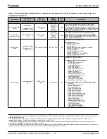
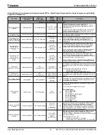
Table 23: Bit Description for Enfinity Large Two Compressor (Models CCH/CCW and LVC/LVW), Continued
Bit
Number
Bit Description
Setting
Description
Unit Controller Jumpers
22 & 23
Dehumidification/Cooling Options
(2 Jumpers)
Jumper 5 = Open (0)
None
Jumper 6 = Open (0)
Jumper 5 = Shorted (1)
Hot Gas/Water Reheat (HGR)
Jumper 6 = Open (0)
Jumper 5 = Open (0)
Hydronic Cooling (waterside economizer)
Jumper 6 = Shorted (1)
24
Not Used
Jumper 7 = Open (0)
25
Lead Compressor Option
Jumper 8 = Open (0)
Compressor #1 is lead
Jumper 8 = Shorted (1)
Compressor #2 is lead
I/O Expansion Module Inputs
26
Compressor #2 Low Pressure Switch
Switch Closed (1)
Low Pressure Switch for compressor #2 is normal
Switch Open (0)
Low Pressure Switch for compressor #2 is in alarm
27
Compressor #2 High Pressure Switch
Switch Closed (1)
High Pressure Switch for compressor #2 is normal
Switch Open (0)
High Pressure Switch for compressor #2 is in alarm
28
Humidistat Dehumidification /
Cooling Stage #1 Request
Closed (1)
HGR Dehumidification is requested (unit has HGR option)
First stage of cooling is requested
(unit does not have HGR option)
29
Not used
N/A
30
Not used
N/A
31
Previous Unit Heat/Cool/Dehumid Mode
Provided by unit controller
Provides mode awareness in Fan Only state
(0=Heating, 1=Cooling or Dehumidification)
1. This switch is effective only when the network scheduling is not in use.


