C
omprehensIve
d
aTa
T
ables
www.DaikinApplied.com 35
ED 15103-6 • MICROTECH III WSHP UNIT CONTROLLER
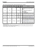
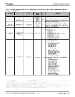
Table 18:
Network Variable Inputs (NVIs) - SmartSource Single and Two Stage Compressor and Enfinity Large Two
Compressor
Point Name
l
on
W
orks
Variable
(NV Index
2
)
SNVT Type
(SNVT Index)
Range/
Default
(in Units)
Heart-
beat
Description
Network Variable Inputs (NVIs)
Application Mode
Input
nviApplicMode
(9)
SNVT_hvac_mode
(108)
Default: HVAC_
NUL
Recv
Sets the unit in an application mode (Auto, Off, Heat, Cool,
Dehumidification, or Fan Only). Application Mode does not
“force” the unit into any state. However, it disables certain
unit operation. For example, an Application Mode of Cool
disables heating; Heat disables cooling and dehumidification;
Fan Only disables heating, cooling, and dehumidification.P3
PnviApplicMode overrides the local room sensor’s System
Mode Switch (Heat/Cool/Auto). The local System Mode
Switch is only used when nviApplicMode is set to HVAC_NUL.
The network override will revert back to its default value upon
unit controller reboot.
Supported Values
0 = HVAC_AUTO
1 = HVAC_HEAT
3 = HVAC_COOL
6 = HVAC_OFF
9 = HVAC_FAN_ONLY
14 = HVAC_DEHUMID
-1 (0xFF) = HVAC_NUL
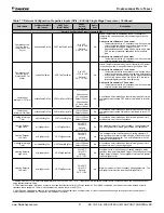
Auxiliary Heat Enable
Input
nviAuxHeatEnable
(10)
SNVT_switch
(95)
Default: Null
Recv
Enables or disables auxiliary heat units with electric heat.
Electric heat is always enabled when it is the only source
of heating, and is unaffected by this variable. The default
state is Null, in which case auxiliary heat is enabled.
3
The
network override will revert back to its default value upon unit
controller reboot.
Selection State Value
Disabled 0 NA
Disabled 1 0%
Enabled 1 0.5 to 100%
Null -1 0%
Clear Alarm
nviClearAlarm
(14)
SNVT_switch
(95)
Default: Normal
No
Clears the Current Alarm. The alarm that is cleared moves
to the Previous Alarm buffer. The value automatically clears
after a Clear Alarm command is issued. The unit controller
automatically returns both the state and value parameters to 0
once the alarm is cleared.
Selection State Value
Normal 0 0%
Clear Alarm NA 0.5 to 100%
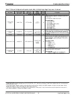
Compressor Enable
nviComprEnable
(11)
SNVT_switch
(95)
Default: Null
Recv
Specifies if the compressor(s) are allowed to operate, which
can be based on proof of loop fluid flow. The loop pump must
be running to provide adequate flow through the unit so the
compressor(s) can operate safely. The network override will
revert back to its default value upon unit controller reboot.
Selection State Value
Disabled 0 NA
Disabled 1 0%
Enabled 1 0.5 to 100%
Null -1 0%
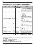
Compressor #1
Runtime Totalizer
nviComp1Hours
(22)
SNVT_count
(8)
0 to 65535 counts
Default: 0
No
Total compressor (SmartSource, Series2) or compressor #1
(Enfinity Large Two Compressor, SS2C) runtime hours.
4
Compressor #1 Starts
Totalizer
nviComp1Starts
(23)
SNVT_count
(8)
0 to 65535 counts
Default: 0
No
Total compressor (SmartSource, Series2) or compressor #1
(Enfinity Large Two Compressor, SS2C) starts.
4
Compressor #2
Runtime Totalizer
nviComp2Hours
(24)
SNVT_count
(8)
0 to 65535 counts
Default: 0
No
Total compressor high capacity (SmartSource, Series2)
(Series2) or compressor #2 (Enfinity Large Two Compressor,
SS2C) runtime hours.
4
Compressor #2 Starts
Totalizer
nviComp2Starts
(25)
SNVT_count
(8)
0 to 65535 counts
Default: 0
No
Total compressor high capacity (SmartSource, Series2) or
compressor #2 (Enfinity Large Two Compressor, SS2C)
starts.
4
1. Analog Null (0x7FFF) is a discrete temperature value of 621.806ºF/327.67ºC. Its purpose is to indicate a sensor failure condition or when the unit controller is not
using that temperature value.
2. The Network Variable index number is a unique identifier for certain
L
on
W
orks
variables. Some BAS companies use this numeric value instead of text to
reference these variables. The NV index number can also be found in the XIF file.
3. After Receive Heartbeat is enabled, this variable reverts to the default (non-override) value if it is not refreshed often enough through a network command or if
communication is disabled (i.e. the device is disabled or is offline).
4. The totalizer continues to increment until the maximum count is reached, at which point the BAS must reset the value by issuing a write command. The variable is
saved in nonvolatile memory every 24 hours. If power is lost, that day’s totalizer information is not stored.


