34
T
WO
-W
IRE
O
UTDOOR
, F
OUR
-W
IRE
I
NDOOR
W
IRING
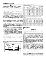
Two wires can be utilized between the indoor and outdoor units.
For this wiring scheme, only the data lines, 1 and 2, are needed
required between the indoor and outdoor units. A 40VA, 208/
230 VAC to 24VAC transformer must be installed in the out-
door unit to provide 24VAC power to the outdoor unit’s elec-
tronic control. See the instruction manual provided with the
thermostat for wiring instructions.
NOTE:
Use of a transformer is recommended if installing a dual
fuel/fossil fuel system or anytime a CTK03/4 is used with a
non-inverter split unit. Failure to use the transformer in the
outdoor unit could result in over loading of the furnace transformer.
1
2
R C
1
2
R C
CTK0*
Thermostat
ComfortNet Compatible
Furnace Integrated
Control Module
ComfortNet Compatible
AC/HP Integrated
Control Module
40VA Transformer
208/230 VAC
24 VAC
1
2
R C
System Wiring using Two-Wires between Furnace and AC/HP
and Four-Wires between Furnace and Thermostat
C
OMFORT
N
ET
™ C
OMPATIBLE
F
URNACE
WITH
N
ON
-
C
OMFORT
N
ET
COMPATIBLE
S
INGLE
-S
TAGE
A
IR
C
ONDITIONER
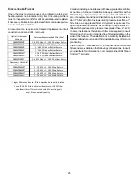
Four wires are required between the furnace and thermostat. Two
wires are required between the furnace control and single stage air
conditioner. For this system configuration, the “Y1” terminal on the
integrated furnace control becomes an output rather than an input.
The “Y1” connection to the outdoor unit is made using both 4-
position thermostat connectors in the CTK0* kit. Remove the red
keying tabs from the on-board connector block and position both
4-position connectors such that “1”, “2”, “R”, “C”, and “Y1” positions
are filled.
1
2
R C
C
Y
ComfortNet Compatible
Furnace Integrated
Control Module
CTK0*
Thermostat
Non-
Compatible
Single Stage AC
ComfortNet
G
W1 W2
Y1
Y2
O
1
2
R
C
4-Position Connectors
from CTK0*
Thermostat Kit
System Wiring between Furnace and Non-Communicating
Compatible Single Stage Air Conditioner
NOTE:
When using a non-communicating condenser, cooling
CFM will need to be set up in the communicating thermostat.
Go to the ComfortNet™ menu > communicating equipment >
furnace > setup > non - comm. Select the condenser size from
the list 18,000 - 60,000 for proper cooling CFM.
C
OMFORT
N
ET
™ S
YSTEM
A
DVANCED
F
EATURES
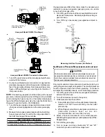
The ComfortNet system permits access to additional system
information, advanced setup features, and advanced diagnos-
tic/troubleshooting features. These advanced features are or-
ganized into a menu structure. The menus are accessed and
navigated by means of the CTK0* thermostat. For details, see
the thermostat instruction sheet.
T
HERMOSTAT
M
ENU
If this furnace is installed with a communicating compatible
heat pump, the system is recognized as a dual fuel system.
The balance point temperature should be set via the thermo-
stat advanced menu.
D
IAGNOSTICS
Accessing the furnace’s diagnostics menu provides ready ac-
cess to the last six faults detected by the furnace. Faults are
stored most recent to least recent. Any consecutively repeated
fault is stored a maximum of three times. Example: A clogged
return air filter causes the furnace limit to trip repeatedly. The
control will only store this fault the first three
consecutive
times
the fault occurs. Navigate to the diagnostics menu as described
in the thermostat installer manual.
NOTE:
It is highly recommended that the fault history be cleared
when performing maintenance or servicing the furnace.
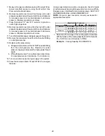
W1 W2 Y1
Y2
O
DEHUM
24 vac "G" input to Furnace
Integrated Control module From
ERV / HRV or Similar Devices
1
1
2
R
C
2
Furnace Integrated
Control Module
R
C
G
CTK0* Thermostat
4-Pin (X2), 7 Pin, or 9 Pin Connector
Содержание DM80VC
Страница 51: ...51 THIS PAGE LEFT INTENTIONALLY BLANK...


