18
Contractor Responsibility
The installing contractor must be certain that:
• All supply and return air ductwork is in place, properly
sealed, and corresponds with installation instructions.
• All thermostats are mounted and wired in accordance
with installation instructions.
• All electric power, all gas, hot water or steam line
connections, and the condensate drain installation
have been made to each unit on the job. These
main supply lines must be functional and capable of
operating all units simultaneously.
• Requirements are met for venting and combustion air.
•
Air filters are in place.
• Input rate and temperature rise are adjusted per rating
plate.
Roof Curb Installation Check
Inspect the roof curb for correct installation. The unit and
curb assembly should be level. Inspect the flashing of the
roof mounting curb to the roof, especially at the corners, for
good workmanship. Also check for leaks around gaskets.
Note any deficiencies in a separate report and forward to
the contractor.
Obstructions, Fan Clearance and Wiring
Remove any extraneous construction and shipping
materials that may be found during this procedure. Rotate
all fans manually to check for proper clearances and that
they rotate freely. Check for bolts and screws that may
have jarred loose during shipment to the job site. Re-
tighten if necessary. Re-tighten all electrical connections.
Field Duct Connections
Verify that all duct connections are tight and that there is no
air bypass between supply and return.
Filter Section Check
Remove filter section access panels and check that filters
are properly installed. Note airflow arrows on filter frames.
Pre-startup Precautions
Transformer and Induced Draft Motor
NOTE: On the 208/230 volt units only.
Ensure the transformer and induced draft motor are set on
the appropriate voltage taps. Both the transformer tap and
induced draft motor are set on 230v from the factory. To
change the induced draft motor voltage, remove the black
induced draft motor wire from the unused terminal on the
ignition control board and swap it with the red wire coming
from the induced draft motor.
It is important to your safety that the unit has been properly
grounded during installation. Check ground lug connection
in main control box for tightness prior to closing circuit
breaker or disconnect switch. Verify that supply voltage
on line side of disconnect agrees with voltage on unit
identification plate and is within the utilization voltage
range as indicated in Appendix B Electrical Data.
System Voltage -
That nominal voltage value assigned
to a circuit or system for the purpose of designating its
voltage class.
Nameplate Voltage -
That voltage assigned to a piece of
equipment for the purpose of designating its voltage class
and for the purpose of defining the minimum and maximum
voltage at which the equipment will operate.
Utilization Voltage -
The voltage of the line terminals
of the equipment at which the equipment must give fully
satisfactory performance. Once it is established that supply
voltage will be maintained within the utilization range under
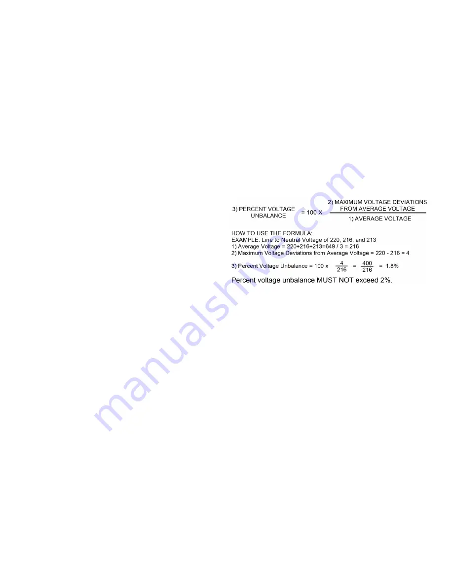
all system conditions, check and calculate if an unbalanced
condition exists between phases. Calculate percent voltage
unbalance as follows.
Three Phase Models Only
Control Voltage Check
Close the disconnect switch to energize control
transformer. Check primary and secondary (24V) of control
transformer.
AIR FLOW ADJUSTMENTS
When the final adjustments are complete, the current
draw of the motor should be checked and compared to
the full load current rating of the motor. The amperage
must not exceed the service factor stamped on the motor
nameplate. The total airflow must not be less than that
required for operation of the furnace.
If an economizer is installed, check the unit operating
balance with the economizer at full outside air and at
minimum outside air.
NOTE: Never run high stage CFM below 300
CFM per ton evaporator freezing or poor unit
performance is possible.
EEM - Standard Static Drive Motor
Adjust the CFM for the unit by changing the position of
the low voltage leads on the terminal block TB1. Refer to
Appendix A for blower performance at each speed tap. The
table below shows RECOMMENDED SPEED TAPS for
heating and cooling. Refer to Appendix D for maximum and
minimum allowed airflow for heating and cooling.


