


4
Set-up and installation
Installation and maintenance instructions
24
Daikin Altherma EHS(X/H)(B)-D
Heat pump (indoor unit) with integrated heat accumulator
008.1444099_01 – 11/2018 – EN
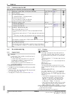
X1M
L
N
COM
PE
1
2
3
PE
COM
3
2
N
1
L
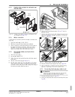
Fig. 4-35
Connecting the heat pump outdoor unit
INFORMATION
If the heat pump outdoor unit is shut off via a circuit spe-
cified by the utility company, the indoor unit is not shut off.
4.7.6
Connecting the outside temperature
sensor (optional)
The heat pump outdoor unit has an integrated outside temperature
sensor which is used for weather-compensated inflow temperature
control with frost protection function. The weather-compensated in-
flow temperature control can be further optimised with the optional
outside temperature sensor.
▪ Choose a location at about one third of the building height (min-
imum distance from floor: 2 m) at the coldest side of the building
(North or North-East). Ensure that the location is not near to any
external heat sources (flues, air ducts), nor subject to direct solar
radiation.
▪ Place outside temperature sensors in such a way that the cable
exit points face downwards (prevents humidity ingress).
CAUTION
Laying the sensor and mains lines in parallel within an in-
stallation conduit can lead to major malfunctions during
controlled operation of the indoor unit.
▪ Always lay the sensor line separately.
1
Connect the outside temperature sensor to a twin-core sensor
line (minimum diameter
1 mm
2
).
2
Lay the sensor line to the indoor unit.
3
Follow the installation steps in
Chap. 4.7.4
.
4
Connect the sensor line to terminal strip XTA1 (see
Chap. 4.7.2
).
5
In the controller, RoCon+ HP set the [External temperature
sensor] parameter to "On" s[→ Main menu → Configuration
→ Sensors].
4.7.7
External switching contact
Connecting an external switching contact (
Fig. 4-36
) enables the op-
erating mode of the indoor unit to be switched over.
The current operating mode is switched by a changing resistance
value (
Tab. 4-7
). The changeover of the operating mode is only ef-
fective for a long as the external switching contact is closed.
The operating mode has an effect on the direct circuit of the indoor
unit as well as all other heating circuits connected to this device as
an option.
When special functions (e.g. "48h Emergency Operation") are activ-
ated, the input is not evaluated.
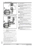
Fig. 4-36
EXT switching contact connection
Operating mode
Resistance RV
Tolerance
Standby
< 680 Ω
± 5%
Heating
1200 Ω
Reducing
1800 Ω
Summer
2700 Ω
Automatic 1
4700 Ω
Automatic 2
8200 Ω
Tab. 4-7
Resistance values for evaluating the EXT signal
INFORMATION
The input is not considered for resistance values greater
than the value for "Automatic 2".
INFORMATION
The [Heating support (HZU)] function integrated in the Ro-
Con+ HP controller (see the Controller operating instruc-
tions) makes it unnecessary to connect the EXT connec-
tion to the burner blocking contact connection of the solar
system.
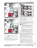
4.7.8
EBA (external requirement request)
By connecting the EBA switching contact to the indoor unit
(
Fig. 4-37
) and corresponding parametrisation in its RoCon+ HP
controller, an external switching contact can be used to generate a
heat request. If the switching contact is closed, the indoor unit
switches to heating mode. The feed temperature is regulated to the
temperature set in the [Feed temperature heating mode] parameter
[→ Main menu → Configuration → Heating].
The EBA switching contact has priority over a request from the room
thermostat.
The switching contact is not evaluated in cooling mode, standby,
manual or summer mode. The heating limits are also ignored.
Fig. 4-37
EBA switching contact connection
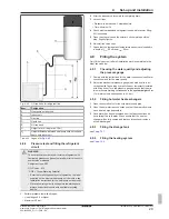
4.7.9
Connecting an external heat generator
INFORMATION
To connect an external heat generator, the connection set
for external heat generators must be installed. (see
Chap. 4.5
).
Содержание Altherma 3 ECH2O
Страница 2: ......
Страница 68: ...008 1444099_01 11 2018 EN Copyright Daikin ...


