370
5.8.5.3 Display
Display interface includes GUI, TV adjust, Tour and zero-channel encoding.
5.8.5.3.1 Display
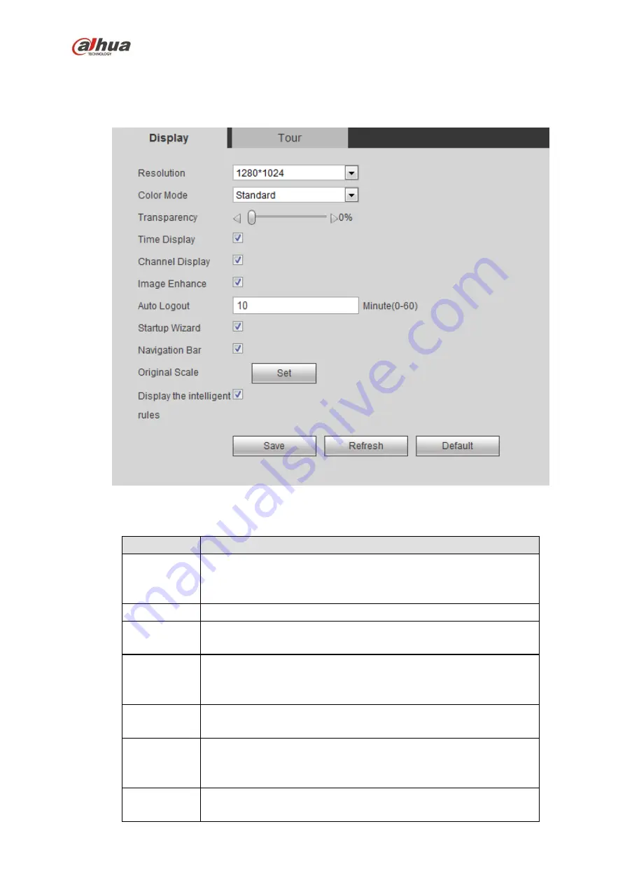
Here you can set background color and transparency level. See Figure 5-106.
Figure 5-106
Please refer to the following sheet for detailed information.
Parameter
Function
Resolution
There
are
four
options:
1920×1080,
1280×1024(default),
1280×720, 1024×768. Please note the system needs to reboot to
activate current setup.
Color mode
Please select from the dropdown list.
Transparency Here is for you to adjust transparency. The value ranges from 128
to 255.
Time
title/channel
title
Check the box here, you can view system time and channel
number on the monitor video.
Image
enhance
Check the box; you can optimize the margin of the preview video.
Startup
wizard
Once you check the box here, system will go to the startup wizard
directly when the system restarts the next time. Otherwise, it will go
to the login interface.
Navigation
bar
Check the box here, system displays the navigation bar on the
interface.
Содержание NVR4204-P-4KS2
Страница 159: ...144 Figure 3 3 3 5 4 NVR11HS 41HS W S2 Series Please refer to Figure 3 4 for connection sample ...
Страница 160: ...145 Figure 3 4 3 5 5 NVR41HS W S2 Series Please refer to Figure 3 5 for connection sample ...
Страница 163: ...148 Figure 3 7 3 5 8 NVR42N Series Please refer to Figure 3 8 for connection sample Figure 3 8 ...
Страница 171: ...156 Figure 3 18 3 5 19 NVR78 Series Please refer to Figure 3 19 for connection sample ...
Страница 172: ...157 Figure 3 19 3 5 20 NVR78 16P Series Please refer to Figure 3 20 for connection sample ...
Страница 173: ...158 Figure 3 20 3 5 21 NVR78 RH Series Please refer to Figure 3 21 for connection sample ...
Страница 174: ...159 Figure 3 21 3 5 22 NVR70 Series Please refer to Figure 3 22 for connection sample ...
Страница 175: ...160 Figure 3 22 3 5 23 NVR70 R Series Please refer to Figure 3 23 for connection sample ...
Страница 176: ...161 Figure 3 23 3 5 24 NVR42V 8P Series Please refer to Figure 3 24 for connection sample ...
Страница 177: ...162 Figure 3 24 ...
Страница 188: ...173 Figure 4 19 Click smart add button you can see device enables DHCP function See Figure 4 20 Figure 4 20 ...
Страница 243: ...228 Figure 4 89 Figure 4 90 ...
Страница 244: ...229 Figure 4 91 Figure 4 92 ...
Страница 259: ...244 Figure 4 110 Figure 4 111 ...
Страница 260: ...245 Figure 4 112 Figure 4 113 ...
Страница 261: ...246 Figure 4 114 Figure 4 115 ...
Страница 263: ...248 Figure 4 117 Figure 4 118 ...
Страница 290: ...275 Figure 4 148 In Figure 4 148 click one HDD item the S M A R T interface is shown as in Figure 4 149 Figure 4 149 ...
Страница 355: ...340 Figure 5 55 Figure 5 56 ...
Страница 356: ...341 Figure 5 57 Figure 5 58 Figure 5 59 ...
Страница 367: ...352 Figure 5 73 Figure 5 74 ...


