background image

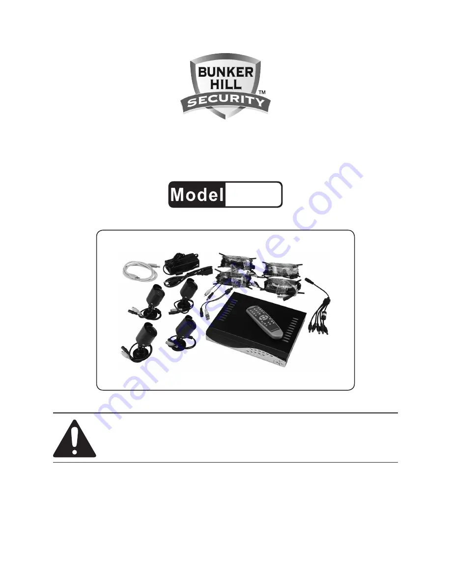
4 channel surveillance 

dvr kit

  with 4-ir cameras

67139

set up and Operating instructiOns

visit our website at: http://www.harborfreight.com

 read this material before using this product. 

Failure to do so can result in serious injury. 

save this manual.

Copyright

©

 2009 by Harbor Freight Tools

®

.  All rights reserved.  No portion of this manual or any artwork 

contained  herein  may  be  reproduced  in  any  shape  or  form  without  the  express  written  consent  of 

Harbor Freight Tools.  Diagrams within this manual may not be drawn proportionally.  Due to continuing 

improvements,  actual  product  may  differ  slightly  from  the  product  described  herein.   Tools  required  for 

assembly and service may not be included.

For technical questions or replacement parts, please call 1-800-444-3353.

manual revised 10h

Содержание 67139

Страница 1: ...ll rights reserved No portion of this manual or any artwork contained herein may be reproduced in any shape or form without the express written consent of Harbor Freight Tools Diagrams within this manual may not be drawn proportionally Due to continuing improvements actual product may differ slightly from the product described herein Tools required for assembly and service may not be included For ...

Страница 2: ...NITOR CONNECTION 11 Starting the DVR 12 OPERATING INSTRUCTIONS 13 RECORDING 13 PLAYBACK 14 NETWORK SETUP 15 What you will need to set up The DVR Online 15 Connecting Your DVR to the Router 15 Finding your DVR s Internal IP Address 15 Preparing Your Computer for Viewing the DVR 16 Installing Software 16 Adding DVR to Trusted Sites 16 Viewing Your DVR Outside of Your Network 17 Programming the DVR 1...

Страница 3: ... the safety alert symbol indicates a hazardous situation which if not avoided could result in minor or moderate injury NOTICE is used to address practices not related to personal injury CAUTION without the safety alert symbol is used to address practices not related to personal injury General Safety Warnings WARNING Read all safety warnings and instructions Failure to follow the warnings and instr...

Страница 4: ...agnetic fields in close prox imity to heart pacemaker could cause pacemaker interference or pacemak er failure In addition people with pacemakers should Avoid operating alone Do not use with power switch locked on Properly maintain and inspect to avoid electrical shock Any power cord must be properly grounded Ground Fault Circuit Inter rupter GFCI should also be imple mented it prevents sustained ...

Страница 5: ...ding provides a low resistance path to carry electricity away from the user reducing the risk of electric shock See 3 Prong Plug and Outlet The grounding prong in the plug is 2 connected through the green wire in side the cord to the grounding system in the tool The green wire in the cord must be the only wire connected to the tool s grounding system and must never be attached to an electrically l...

Страница 6: ...ou are using one extension cord 5 for more than one tool add the nameplate amperes and use the sum to determine the required minimum cord size See Table A If you are using an extension cord 6 outdoors make sure it is marked with the suffix W A W in Canada to indicate it is acceptable for outdoor use Make sure the extension cord is prop 7 erly wired and in good electrical con dition Always replace ...

Страница 7: ... for longer range all are color in daylight and black white infrared night viewing Camera Cables Remote Control USB Cable Cable Splitter Power Cord Power Adapter Software CD Two AAA Batteries NOTICE Camera surveillance may be prohibited by laws that vary from state to state Check laws in your area before using for surveillance This device complies with part 15 of the FCC Rules Operation is subject...

Страница 8: ...ents Software CD Batteries Cameras Power Adapter Power Cord Camera Cables Cable Splitter DVR USB Port Remote Control USB Cable Figure 1 Figure 2 Front Panel 1 3 14 15 16 17 2 4 13 5 12 6 11 7 10 8 9 1 PWR LED indicates unit is on HDD LED indicates hard drive is in 2 use CH1 3 Channel 1 CH2 4 Channel 2 CH3 5 Channel 3 CH4 6 Channel 4 Quad 7 View all channels REW 8 Rewind in playback mode PAUSE 9 Pa...

Страница 9: ...itor connec tion CH1 5 Camera 1 connection CH2 6 Camera 2 connection CH3 7 Camera 3 connection CH4 8 Camera 4 connection POWER INPUT JACK 9 12V DC Connector from main power adapter 0 9 Number Keys 1 4 Channel Select All Display All Channels Menu Enter Exit Menu Up Down Left Right SEL Select Rewind Play Forward Record Pause Playback Stop Audio Search Search or switch audio channels Mute Turn on off...

Страница 10: ...re specific soft ware requirements and you will need to have an understanding of your mo dem your computer and your internet connection settings as well as port forwarding knowledge Following are the possible set up options DVR with a TV monitor sold sepa 1 rately This is the simplest set up that allows you to adjust all the set tings view and record live images and play back any recordings You do...

Страница 11: ...and push the BNC Connector in so the pins slide into the slots Turn the connector clockwise to lock b the pins in place Attach the black power connector at 5 the BNC end of the same cable to one of the remaining Cable Splitter connectors Attach the connectors at the other 6 end of the Camera Cable to the same color connectors of one of the Cam eras Repeat steps 4 through 6 for each of 7 the other ...

Страница 12: ...ve and show the hard drive information If there is any problem with the hard drive the DVR will display the infor mation and will not finish its boot up program checking hdd master maxtOr s tm3250310a new dvr FOrmat hdd cOnFirm select FOrmat menu cancel Note When detecting a new hard drive the DVR will prompt you to format the hard drive Press SEL to format the new hard drive or MENU to cancel and...

Страница 13: ...he DOWN button The audio signal will continue to record and can be heard in playback mode RECORDING MODE One of the following will display along the bottom left of the screen A REC Normal recording S REC Motion sensor recording N REC No recording OTHER DATA The following will display along the remaining lower edge of the screen M or S Indicates which hard drive is in use M Master S slave Displays ...

Страница 14: ...rts are the number of hours of record time For instance in the top chart Type NTSC if you set the unit to a total of 60 fps and the quality to High you will be able to record for 88 hours to a hard drive which has 160GB of available space A larger hard drive will allow for more recording time PLAYBACK To watch recorded videos you will need to enter Playback mode To en ter Playback mode first press...

Страница 15: ...view the DVR for initial set up but is not needed for remote access once the unit is set up and working prop erly Connecting Your DVR to the Router Power off the DVR by removing the 1 power cable from the back of the DVR Connect the network cable sold 2 separately to the back of the DVR in the Ethernet port Connect the other end of the network 3 cable to an available port on the router The port sh...

Страница 16: ...ettings of the web browser To install the PC Viewer program Insert Software CD into your com 1 puter s CD ROM drive Open the CD directory 2 Double click on DxClient 2 7 1 3 ENG Run the Install program 4 Follow the setup wizard to finish the installation Adding DVR to Trusted Sites Every computer that is accessing the DVR will need to be configured to download and run ActiveX con trols This is a on...

Страница 17: ...m to use the software Viewing Your DVR Outside of Your Network Once you have successfully set up and viewed your DVR through a router you are now able to set up your router to view the DVR while at a remote location This process is called Port Forwarding Port Forward ing is required if you want to view the DVR from a computer that is not connected to the same router This process opens a path on yo...

Страница 18: ...UAGE ENGLISH RESET MENU MOVE SEL SELECT MENU EXIT 1 Press Menu to enter the Main Menu To access the menu options and 2 make selections within the Main Menu and Sub Menus Press up and down to select items a Press SEL to change an option b Press MENU to save any changes c and return to the previous Menu CHANNEL CAMERA SETUP 1 o n 2 o n channel setup 3 o n 4 o n Move SEL Select MENU Esc The Channel C...

Страница 19: ...FPS 3 2 5FPS 4 3FPS MOVE SEL MENU EXIT The total number of photos taken per second is divided among the cameras The total frame rate of all the cameras in use is set to 60fps frames per second The higher set tings produce better images but use up more hard drive space In the Record Frame Rate sub menu 1 press the arrow keys and to select a channel camera Press SEL to increase or STOP 2 to decrease...

Страница 20: ...ustomize the recording time for the cameras The cameras are all set to the same schedule The time line shows a 24 hour period based on AM PM 0 12 In the Record Schedule sub menu 1 press the arrow keys and to move the marker to the de sired time Press SEL to modify the recording 2 mode The Mode options are NO RECORD white The DVR will a not record during this period NORMAL RECORD red The DVR b will...

Страница 21: ...rm will sound for the num c ber of seconds indicated The alarm can be set to 5 10 15 20 25 or 30 seconds Press SEL to increase or STOP to decrease the number MOTION DETECTOR SETUP motion detector setup CH1 ON Level 2 Area CH2 ON Level 2 Area CH3 ON Level 2 Area CH4 ON Level 2 Area MOVE SEL SELECT MENU ESC This sub menu allows you to set the motion detection options for each camera In the Sensor Se...

Страница 22: ...eo once the hard drive is full and it allows you to format the hard drive It also shows hard drive size and how much memory is used In the Main Menu press the up or 1 down arrow keys to select Hard Drive Setup Press SEL to enter the Hard Drive 2 Setup sub menu OVERWRITE ENABLE DISABLE hard drive setup OVERWRITE ENABLED ON MAXTOR STM250310AS MASTER HDD SIZE 250203MB MASTER HDD USED 124931MB 50 MAST...

Страница 23: ... it down and keep it in a safe place so you do not forget the new password To change the password In the Miscellaneous Setup sub 1 menu press the arrow keys to select Change Password Press SEL to enter the sub menu 2 CURRENT PASSWORD NEW PASSWORD COMFIRM PASSWORD 3 Enter the current password first then enter the new password Re enter the new password to confirm Note The password must be 6 charac t...

Страница 24: ... the channel 2 number to hide Press MENU to save and return to 3 the previous menu AUDIO PORT SETUP audio port setup AUDIO PORT1 VIDEO CHANNEL AUDIO PORT1 RECORD MOVE SEL SELECT MENU EXIT 1 OFF To set up the Audio Port first check to see which camera you have set up with a microphone sold separately To enable the audio recording func tion In the Miscellaneous Setup sub 1 menu press the arrow keys ...

Страница 25: ... CON Contrast BRI Brightness HUE Hue SAT Saturation Press MENU to save and return to 4 the previous menu PASSWORD ENABLE You will always need the current password to format the hard drive to reset the menu or to access the customer port To access other parts of the system you can enable or dis able the password To turn password access on or off In the Miscellaneous Setup sub 1 menu press the arrow...

Страница 26: ...ss the arrow keys to select Seq Dwell Time Press SEL to choose between off 2 and one of the time settings VIDEO LOSS SOUND The Video Loss Sound function turns a buzzer on or off which will sound if one of the cameras is not properly connected To set this function on or off In the Miscellaneous Setup sub 1 menu press the arrow keys to select Video Sound Loss Press SEL to choose between off 2 and on...

Страница 27: ...nu press the up or 1 down arrow keys to select Network Setup Press SEL to enter the Network 2 Setup sub menu MAC Address This indicates the DVR network port s physical address IMPORTANT The MAC Media Access Control address is your computer s unique hardware identity code This setting should only be changed if multiple DVRs are being setup on the same network The first part of the code must not be ...

Страница 28: ... the number to change Press the arrow keys 4 to change the number Press SEL to accept the change 5 Press STOP 6 to delete a number Press 7 REC to insert a number Press MENU to save and return to 8 previous menu Note Before using your web browser to view the program over the network you may need to change the security settings and enable all ActiveX func tions SUBNET MASK The Subnet Mask is the ide...

Страница 29: ...r chang ing the IP Address numbers to make any changes to the Subnet Mask USER SETUP When accessing the DVR from a remote location you will be prompted for a login and password The default login is admin for full administrator rights and the default password is 111111 You can set an additional user ID and password to setup a user with limited access allowing only viewing of live video over a netwo...

Страница 30: ...e call 1 800 444 3353 Page 30 DDNS SETUP If you require an external service to maintain a dynamic IP address enter the user information here Follow the same steps as for chang ing the IP Address numbers to make any changes to the Subnet Mask ...

Страница 31: ... drive FILE Play Mode Plays a video from 4 the file you choose in another storage location NET Play Mode Plays video remote 5 ly over the internet or intranet Event list Lists the recorded videos 6 Program Local Setting Configuration 7 window for settings Remote DVR Control 8 Switch between Storage Devices 9 Capture Image 10 BACKUP 11 Controls 12 through 20 allow manipu lation of the selected vide...

Страница 32: ...ave the file as AVI or MSC To enter the Configuration Window 1 click on Program Local Setting Make any adjustments needed then 2 click SAVE PLAYING OR BACKING UP A VIDEO 3 To play or backup a video click EVENT list to open a list of files Locate the desired video Click PLAY 4 to play the video To Backup the video click BACKUP 5 after clicking PLAY To stop the backup click BACKUP 6 again To Stop pl...

Страница 33: ...l will only be able to access viewing of live video Click on NET Play Mode to exit the 4 remote DVR WEB BROWSER REMOTE CONTROL DVR This mode allows you to connect to the DVR through your web browser Enter the IP address and domain 1 name of remote DVR in the address bar Note If the port number is not 80 add the port number before the IP address or domain name You will be prompted for the same 2 in...

Страница 34: ... 3 remote DVR Audio Connection To add audio to one of the camera locations plug a microphone sold separately into the Audio Input jack on the back of the DVR Route the microphone to the chosen camera Hard Disk Installation An additional hard disk can be con nected to this unit Consult your hard drive manual for installation and have installed by a qualified technician Note Do not disconnect the ha...

Страница 35: ...d before further use Cleaning and Maintenance BEFORE EACH USE inspect the general condition of the unit includ ing connections wiring and cameras Check for loose or damaged hard ware damaged electrical wiring and any other condition that may affect its safe operation WARNING If the supply cord of this DVR is damaged it must be replaced only by a qualified ser vice technician NTSC PAL Output Select...

Страница 36: ...nly shows up on playback Misc Setup Adjust Image Parameters for clearest im i age Cannot access connected modem Loose or incorrect 1 connections Incorrect address 2 information Check that the connections are secure and plugged into the 1 correct location in the correct order Through the Main Menu under Network Setup 2 Check that IP Allocation is set to DHCP Note the IP Address Enter the IP Address...

Страница 37: ...ress of the modem to complete this step Check for correct external IP address 2 Check firewall settings 3 Add to allowed IP addresses 4 Buzzer sounding One or more of the cameras are not connected Check that all the camera wiring is completely plugged in at all connection points Poor quality images 1 If viewed on TV screen TV settings Camera settings need adjusting Through the Main Menu check that...

Страница 38: ... parts of the product In fact the manufacturer and or distributor expressly states that all repairs and parts replacements should be undertaken by certified and licensed technicians and not by the buyer The buyer assumes all risk and liability arising out of his or her repairs to the original product or replacement parts thereto or arising out of his or her installation of replacement parts theret...

Отзывы: