235
the icon is shown as
. Click
to delete a record type from one period.
In Figure 4-92. Click button
after one date or a holiday, you can see an interface shown as in
Alarm output: when an alarm occurs, system enables peripheral alarm devices.
Latch: when tripwire complete, system auto delays detecting for a specified time. The value ranges
from 1-300(Unit: second)
Show message: System can pop up a message to alarm you in the local host screen if you enabled
this function.
Alarm upload: System can upload the alarm signal to the network (including alarm centre) if you
enabled current function.
Send email: System can send out email to alert you when an alarm occurs.
Record channel: System auto activates tripwire channel(s) to record once an alarm occurs. Please
make sure you have set intelligent record in Schedule interface(Main Menu->Setting->Schedule)
and schedule record in manual record interface(Main Menu->Advanced->Manual Record)
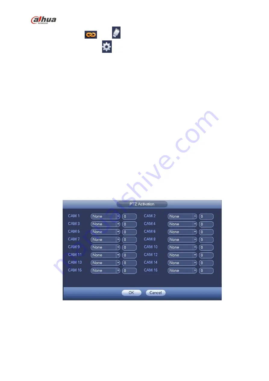
PTZ activation: Here you can set PTZ movement when an alarm occurs. Such as go to preset, tour
&pattern when there is an alarm. Click
“
select
”
button, you can see an interface is shown as in
Record Delay: System can delay the record for specified time after alarm ended. The value ranges
from 10s to 300s.
Tour: Here you can enable tour function when an alarm occurs. System one-window tour.
Snapshot: You can enable this function to snapshot image when a motion detect alarm occurs.
Buzzer: Highlight the icon to enable this function. The buzzer beeps when an alarm occurs.
Figure 4-99
Содержание NVR4204-P-4KS2
Страница 159: ...144 Figure 3 3 3 5 4 NVR11HS 41HS W S2 Series Please refer to Figure 3 4 for connection sample ...
Страница 160: ...145 Figure 3 4 3 5 5 NVR41HS W S2 Series Please refer to Figure 3 5 for connection sample ...
Страница 163: ...148 Figure 3 7 3 5 8 NVR42N Series Please refer to Figure 3 8 for connection sample Figure 3 8 ...
Страница 171: ...156 Figure 3 18 3 5 19 NVR78 Series Please refer to Figure 3 19 for connection sample ...
Страница 172: ...157 Figure 3 19 3 5 20 NVR78 16P Series Please refer to Figure 3 20 for connection sample ...
Страница 173: ...158 Figure 3 20 3 5 21 NVR78 RH Series Please refer to Figure 3 21 for connection sample ...
Страница 174: ...159 Figure 3 21 3 5 22 NVR70 Series Please refer to Figure 3 22 for connection sample ...
Страница 175: ...160 Figure 3 22 3 5 23 NVR70 R Series Please refer to Figure 3 23 for connection sample ...
Страница 176: ...161 Figure 3 23 3 5 24 NVR42V 8P Series Please refer to Figure 3 24 for connection sample ...
Страница 177: ...162 Figure 3 24 ...
Страница 188: ...173 Figure 4 19 Click smart add button you can see device enables DHCP function See Figure 4 20 Figure 4 20 ...
Страница 243: ...228 Figure 4 89 Figure 4 90 ...
Страница 244: ...229 Figure 4 91 Figure 4 92 ...
Страница 259: ...244 Figure 4 110 Figure 4 111 ...
Страница 260: ...245 Figure 4 112 Figure 4 113 ...
Страница 261: ...246 Figure 4 114 Figure 4 115 ...
Страница 263: ...248 Figure 4 117 Figure 4 118 ...
Страница 290: ...275 Figure 4 148 In Figure 4 148 click one HDD item the S M A R T interface is shown as in Figure 4 149 Figure 4 149 ...
Страница 355: ...340 Figure 5 55 Figure 5 56 ...
Страница 356: ...341 Figure 5 57 Figure 5 58 Figure 5 59 ...
Страница 367: ...352 Figure 5 73 Figure 5 74 ...


