


282
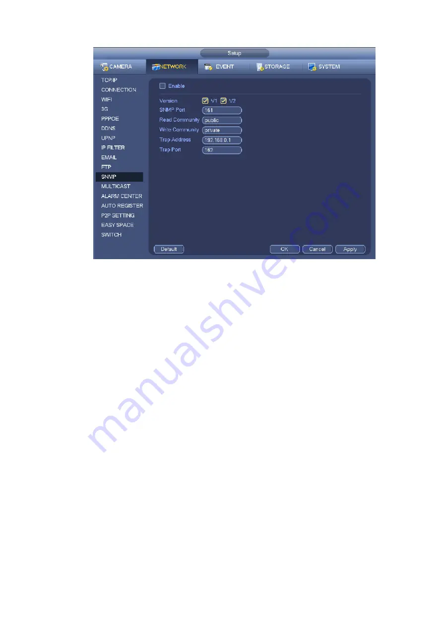
Figure 4-174
Please enable the SNMP function. Use the corresponding software tool (MIB Builder and MG-SOFT MIB
Browser. You still need two MIB file: BASE-SNMP-MIB, NVR-SNMP-MIB) to connect to the device. You
can get the device corresponding configuration information after successfully connection.
Please follow the steps listed below to configure.
In Figure 4-174, check the box to enable the SNMP function. Input the IP address of the PC than is
running the software in the Trap address. You can use default setup for the rest items.
Compile the above mentioned two MIB file via the software MIB Builder.
Run MG-SOFT MIB Browser to load the file from the previous step to the software.
Input the device IP you want to manage in the MG-SOFT MIB Browser. Please set the corresponding
version for your future reference.
Open the tree list on the MG-SOFT MIB Browser; you can get the device configuration. Here you can
see the device has how many video channels, audio channels, application version and etc.
Note
Port conflict occurs when SNMP port and Trap port are the same.
4.8.1.11 Multicast
Multicast setup interface is shown as in Figure 4-175.
Содержание DHI-NVR5224-24P-4KS2
Страница 1: ...Network Video Recorder User s Manual V4 3 2...
Страница 136: ...124 Figure 3 5 3 6 6 NVR42N Series Please refer to Figure 3 6 for connection sample Figure 3 6...
Страница 140: ...128 Figure 3 11 3 6 12 NVR42V 8P Series Please refer to Figure 3 12 for connection sample...
Страница 141: ...129 Figure 3 12...
Страница 155: ...143 Figure 4 15 Step 2 Click device display edit interface See Figure 4 16...
Страница 218: ...206 Figure 4 93 Figure 4 94...
Страница 238: ...226 Figure 4 110 Figure 4 111 Figure 4 112...
Страница 249: ...237 Figure 4 123 Figure 4 124...
Страница 251: ...239 Figure 4 126 Click draw button to draw the zone See Figure 4 127...
Страница 255: ...243 Figure 4 130 Click Draw button to draw a zone See Figure 4 131 Figure 4 131...
Страница 260: ...248 Figure 4 136 Click draw button to draw the zone See Figure 4 137...
Страница 273: ...261 Figure 4 148 Figure 4 149...
Страница 274: ...262 Figure 4 150 Figure 4 151...
Страница 384: ...372 Figure 5 60 Figure 5 61...
Страница 385: ...373 Figure 5 62 Figure 5 63...
Страница 409: ...397 Figure 5 96 Figure 5 97...
Страница 415: ...403 Figure 5 106 5 10 4 4 Record Control The interface is shown as in Figure 5 107 Figure 5 107...