


115
3.4.2
NVR41H/41H-P/41H-8P/21HS-S2/21HS-P-S2/21HS-8P-S2/41HS-W-S2/41HS-4KS
2/41HS-P-4KS2/41HS-8P-4KS2/1AHS/1AHS-4P/1AHS-8P/21HS-4KS2/21HS-P-4K
S2/21HS-8P-4KS2 Series
○
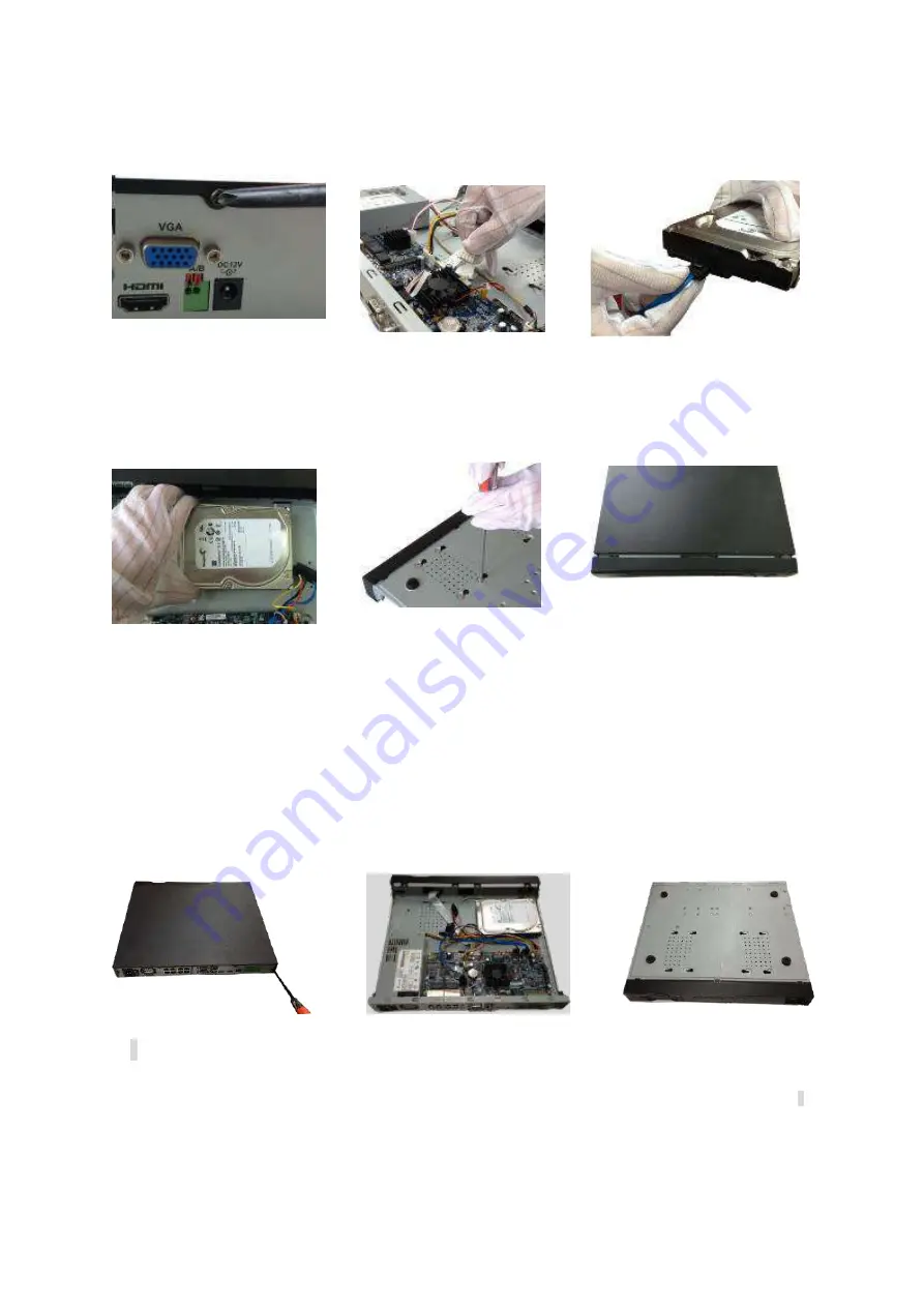
1
. Loosen the screws of the upper
cover and side panel.
○
2
Connect the one end of the
HDD data cable and the power
cable to the mainboard.
○
3
Connect the other end of the
HDD data cable and the power
cable to the HDD.
○
4
Place the HDD in accordance
with the four holes on the bottom of
the chassis.
○
5
Turn the device upside down;
fix the screws to secure the HDD
on the bottom of the chassis.
○
6
Put the cover in accordance
with the clip and then fix the
screws on the rear panel and side
panel.
3.4.3
NVR42/42N/42-P/42-8P/42-16P/42-4K/42-8P-4K/52-4KS2/52-8P-4KS2/52-16P-4K
S2/22-S2/22-P-S2/22-8P-S2/42-4KS2/42-P-4KS2/42-8P-4KS2/42-16P-4KS2/5224-
24P-4KS2/2A16/22-4KS2/22-P-4KS2/22-8P-4KS2/52-16P-4KS2E Series
○
1
Loosen the screws of the rear
panel and side panel.
②
Place the HDD in accordance with
the four holes in the bottom.
③
Turn the device upside down and
then secure the screws firmly. It is to
fix the HDD on the chassis.
Содержание DHI-NVR5224-24P-4KS2
Страница 1: ...Network Video Recorder User s Manual V4 3 2...
Страница 136: ...124 Figure 3 5 3 6 6 NVR42N Series Please refer to Figure 3 6 for connection sample Figure 3 6...
Страница 140: ...128 Figure 3 11 3 6 12 NVR42V 8P Series Please refer to Figure 3 12 for connection sample...
Страница 141: ...129 Figure 3 12...
Страница 155: ...143 Figure 4 15 Step 2 Click device display edit interface See Figure 4 16...
Страница 218: ...206 Figure 4 93 Figure 4 94...
Страница 238: ...226 Figure 4 110 Figure 4 111 Figure 4 112...
Страница 249: ...237 Figure 4 123 Figure 4 124...
Страница 251: ...239 Figure 4 126 Click draw button to draw the zone See Figure 4 127...
Страница 255: ...243 Figure 4 130 Click Draw button to draw a zone See Figure 4 131 Figure 4 131...
Страница 260: ...248 Figure 4 136 Click draw button to draw the zone See Figure 4 137...
Страница 273: ...261 Figure 4 148 Figure 4 149...
Страница 274: ...262 Figure 4 150 Figure 4 151...
Страница 384: ...372 Figure 5 60 Figure 5 61...
Страница 385: ...373 Figure 5 62 Figure 5 63...
Страница 409: ...397 Figure 5 96 Figure 5 97...
Страница 415: ...403 Figure 5 106 5 10 4 4 Record Control The interface is shown as in Figure 5 107 Figure 5 107...