


273
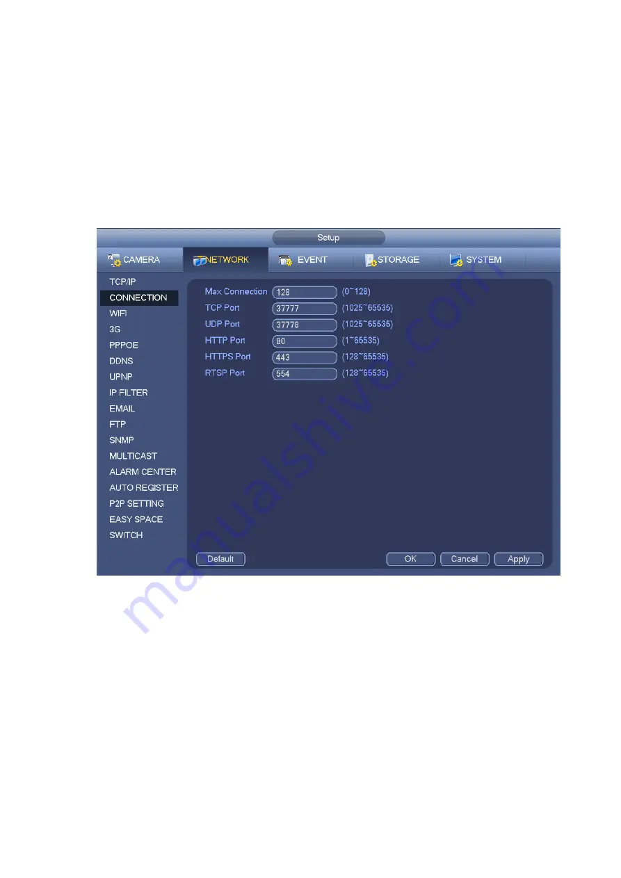
The connection setup interface is shown as in Figure 4-164.
Max connection: The max client login amount (such as WEB, platform, cellphone and etc). The value
ranges from 1 to 128(default).
TCP port: Default value is 37777.
UDP port: Default value is 37778.
HTTP port: Default value is 80.
HTTPS port: Default value is 443.
RTSP port: Default value is 554.
Important: System needs to reboot after you changed and saved any setup of the above four ports.
Please make sure the port values here do not conflict.
Figure 4-164
4.8.1.3 WIFI AP
Note
This function is for some series product only.
4.8.1.3.1 WIFI AP
The WIFI AP interface is shown as below. See Figure 4-165. Here you can set WIFI hotspot, so that the
network camera can use the hotspot to connect to the network.
2.4GHz/5GHz: Please check the box to enable the function.
SSID: It is to set SSID name. You can use this name to search the device.
Password: It is to set SSID password. You can use this password to connect to the network.
Security: Select authentication mode from the dropdown list.
Channel: Please select a channel from the dropdown list. The default setup is auto.
Mode: There three options: high/middle/low. Please select from the dropdown list.
Содержание DHI-NVR5224-24P-4KS2
Страница 1: ...Network Video Recorder User s Manual V4 3 2...
Страница 136: ...124 Figure 3 5 3 6 6 NVR42N Series Please refer to Figure 3 6 for connection sample Figure 3 6...
Страница 140: ...128 Figure 3 11 3 6 12 NVR42V 8P Series Please refer to Figure 3 12 for connection sample...
Страница 141: ...129 Figure 3 12...
Страница 155: ...143 Figure 4 15 Step 2 Click device display edit interface See Figure 4 16...
Страница 218: ...206 Figure 4 93 Figure 4 94...
Страница 238: ...226 Figure 4 110 Figure 4 111 Figure 4 112...
Страница 249: ...237 Figure 4 123 Figure 4 124...
Страница 251: ...239 Figure 4 126 Click draw button to draw the zone See Figure 4 127...
Страница 255: ...243 Figure 4 130 Click Draw button to draw a zone See Figure 4 131 Figure 4 131...
Страница 260: ...248 Figure 4 136 Click draw button to draw the zone See Figure 4 137...
Страница 273: ...261 Figure 4 148 Figure 4 149...
Страница 274: ...262 Figure 4 150 Figure 4 151...
Страница 384: ...372 Figure 5 60 Figure 5 61...
Страница 385: ...373 Figure 5 62 Figure 5 63...
Страница 409: ...397 Figure 5 96 Figure 5 97...
Страница 415: ...403 Figure 5 106 5 10 4 4 Record Control The interface is shown as in Figure 5 107 Figure 5 107...