


- 82 -
14. SPECIFICATIONS (continued)
QUICK MANUAL
For details, refer to “10. OPERATION”.
Before Using the Welding Power Source
1.
Settings of Welding Method
Select “AC TIG”, “AC-DC TIG”, DC
TIG” or “DC STICK” by using the
WELDING METHOD key.
For DC STICK welding, skip steps
1, 2, 3, and 4.
2.
AC WAVE selection
In the case of AC TIG and AC-DC
TIG welding, select “STANDARD”,
“SOFT” or “HARD” with the AC
WAVE selector key.
3. Settings of Crater/Arc Spot
Use the CRATER-FILL key to
select OFF / ON / REPEAT / SPOT.
4. Settings of Functions
٨
For using INITIAL CURRENT, press the INITIAL
CURR. key to set the function to “ON”.
[ON]: INITIAL CURR. lamp is on.
[OFF]: INITIAL CURR. lamp is off.
٨
For pulse welding, set to “ON” by using the PULSE
key.
[ON]: PULSE lamp is on.
[OFF]: PULSE lamp is off.
٨
For LIFT START, set to “ON” by using the LIFT
START key. For HIGH FREQUENCY START, set to
“OFF” with this key.
[ON]: LIFT START lamp is on.
[OFF]: LIFT START lamp is off.
٨
For using SLOPE function, set to “ON” with the
SLOPE selection key.
[ON]: LIFT START lamp is on.
[OFF]: LIFT START lamp is off.
٨
For using the water-cooled torch, set to “WATER”
with the TOCH key, and then run cooling water.
[WATER]: TORCH lamp is on.
[AIR]: TORCH lamp is off.
NOTE:
There may be unavailable functions in some crater
settings. Refer to “OPERATION” for details.
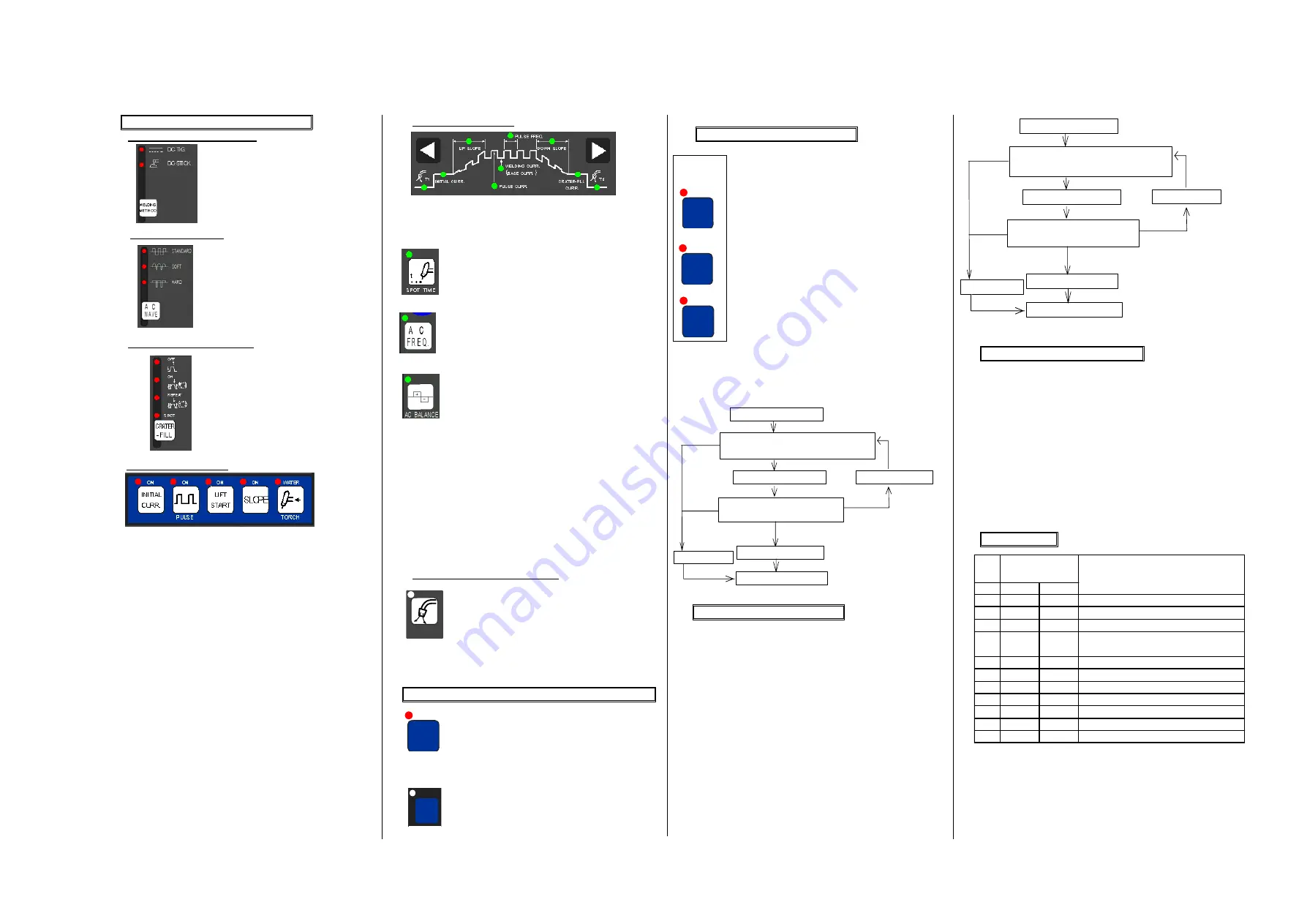
5. Settings of Parameter
Use the parameter selection keys to select the
parameter you want to set, then adjust it while
turning the parameter adjusting knob.
When the arc spot time is set up, select the
key shown in the figure on the left, and then
use the parameter adjusting knob for time
setting.
Using the parameter adjusting knob, adjust
the AC frequency after selecting the key
shown in the figure on the left in the case of
AC TIG and AC-DC TIG welding.
Using the parameter adjusting knob, set up
the EP ratio after selecting the key shown in
the figure on the left so that the required AC
balance is obtained in the case of AC TIG
and AC-DC TIG welding.
NOTE:
٨
Turning the parameter adjusting knob clockwise
increases the parameter. To decrease the
parameter, turn the parameter adjusting knob
counter-clockwise. The parameters largely
increase or decrease by turning the parameter
adjusting knob quickly.
٨
There may be unavailable parameters in some
crater settings and function settings. Refer to
Section 10, “OPERATION” for details
.
6. Checking the Rate of Gas Flow
Open the discharge valve of the gas
cylinder, press the GAS CHECK key to
check the rate of gas flow. After
performing GAS CHECK, stop the gas
flow by pressing the GAS CHECK key.
Now you have completed the preparations that are
required to start welding. Press the torch switch to start
welding.
Protecting the Keys and Releasing the Key Protection
٨
Protecting of the keys
Hold down the ENTER key + the F key at
a time for a few sec. The F lamp starts
blinking. Blinking of the F lamp means the
welding machine is in the key protection
mode.
٨
Releasing the key protection
Hold down the ENTER key + the F key at
a time for a few sec. When the F lamp
turns off, the key protection function is
released.
Presetting the Welding Conditions
1) Pressing the SAVE key enters the save
mode. The preset welding condition
number is displayed in the right display
and the welding current is displayed in
the left display.
2) Preset the welding conditions to the
desired numbers 0 - 30 while turning the
parameter adjusting knob. When “---“ is
displayed in the left display, the number
you selected is available. When “---” is
not displayed in the left display, the
number you selected is unavailable. In
this case, select another number.
Otherwise, the welding conditions preset
to the number are erased and overwritten
with the welding conditions you newly set.
3) Press the ENTER key to check the parameter that is
preset to the number.
4) When pressing the ENTER key again, the welding
conditions are set.
Loading the Welding Conditions
1) Pressing the LOAD key enters the load mode.
The preset welding condition number is displayed
in the right display and the welding current is
displayed in the left display.
2) Preset the welding conditions to the desired
numbers 0 – 30 while turning the parameter
adjusting knob. When “---“ is displayed in the left
display, no welding conditions are preset to the
number you selected.
3) Press the ENTER key to check for the parameter
preset to the number.
4) When pressing the ENTER key again, the
welding conditions preset to the welding condition
number are retrieved.
Settings of the (Internal) Functions
1) When holding down the F key for a few sec., the
function mode is activated. The function number
blinks in the left display, the function status is
displayed in the right display.
2) Set the function number while turning the
parameter adjusting knob.
3) When pressing the F key, the function number
lights up, then the function status blinks.
4) Set the function status while turning the
parameter adjusting knob.
5) To cancel the function mode, hold down the F
key for a few minutes.
Error code table
ENTER
SAVE
LOAD
J O B
MEMORY
GAS
CHECK
㧲
ENTER
Ԙ
ԙ
ԛ
Ԝ
Press the MEMORY key.
Set the welding condition number while
turning the parameter adjusting knob.
Press the parameter selector key
to check the parameter value.
Press the ENTER key.
The memory mode quits
.
The welding conditions are set to the number you selected.
Discontinue
Reset the welding condition number.
Press the ENTER key.
Press the LOAD key.
Press the MEMORY key.
Discontinue
Press the LOAD key.
Set the welding condition number while
turning the parameter adjusting knob.
Press the parameter selector key
to check the parameter value.
Press the ENTER key.
The readout mode quits
.
The welding conditions are set to the number you selected.
Discontinue
Reset the welding condition number.
Press the ENTER key.
Press the SAVE key.
Press the LOAD key.
Discontinue
ԝ
Ԛ
No.
Left
Right
1
dAI
HEn
Torch switch off state waiting
2
E-
000
Operation stop
3
E-
100
Control power supply error
4
E-
200
Primary/secondary current detection
error
5
E-
300
Thermal overload
6
E-
500
Lack of water pressure
7
E-
510
Pump error
8
E-
600
Battery low (warning)
9
E-
710
Lack of phase
10
E-
751
Secondary side over voltage error
11
E-
9XX
Microcomputer error
Displays on the
front panel
Classification of errors
When using this product with a robot of our company,
refer to “Application (arc welding)” in owner’s manual of
the robot.