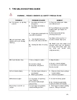
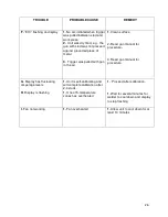
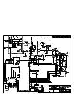
dabotek DT1200i Скачать руководство пользователя страница 35


35 


STUD WELDER 


REPLACEMENT PARTS LIST 
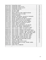


PART 


DWG 

NUMBER  DESCRIPTION 

  REF# 


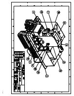
011260-011  TRANSFORMER, MAIN w/PTC, 400V 


011260-013  TRANSFORMER, MAIN w/PTC, 480V 


010440-001  POWER CABLE ASSY, 10AWG, 12.5FT CE 


010490-003  CHASSIS, MAIN 


010520-002  PANEL, REAR - METAL 

  4,5,46 

010511-012  PANEL, UPPER REAR, PLASTIC 


010513-001  PANEL, LOWER REAR, PLASTIC 


010551-013  PANEL, FRONT, PRINTED 


010553-001  LAMP, INDICATOR 


017001-002  KNOB, FOR TIME/CURRENT CONTROL 


010601-001  BOOT, WEATHER, FOR CIRCUIT BREAKER 


13 

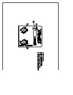
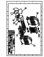
011210-001  CHASSIS, INDUCTOR 


14 

011215-001  FAN ASSY 


15 

011216-001  FAN BLADE 


17 

011220-002  INDUCTOR, OUTPUT 


18 

011230-001  INDUCTOR, MAIN w/ PTC 


19 

011241-001  INDUCTOR, COMMUTATING, FRONT 


20 

011251-001  INDUCTOR, COMMUTATING, REAR 


21 

011272-001  TRANSFORMER, AUXILIARY, 400V 


23 

011272-012  TRANSFORMER, AUXILIARY, 480V 


23 

011300-001  SHUNT, CALIBRATED 


24 

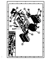
010420-012  ASSY, UPPER REAR PANEL 


25 

019900-002  STRAIN RELIEF 


26 

019900-102  NUT FOR STRAIN RELIEF 


27 

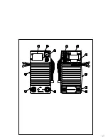
011401-001  ASSY, DIODE & HEATSINK 


30 

011541-001  ASSY, SCR & HEATSINK 


31 

010550-112  ASSY, FRONT PANEL 


32 

011510-012  PC BOARD, MAIN CONTROL 


33 

011520-001  ASSY, INPUT RECTIFIER (CF) 


34 

016411-002  VARISTOR FOR CF ASSY 


35 

011610-002  METER, DIGITAL DISPLAY 


38 

010580-001  CONTROL ASSY, STUD TIME/CURRENT 


39 

101520-001  PC BOARD, STUD GUN CONTROL 


40 

Содержание DT1200i

Страница 1: ...OTEK Birkedam 10 C DK 6000 Kolding Denmark Tlf 45 7550 5666 Fax 45 7550 4795 sales dabotek com www dabotek eu DABOTEK DT1200i P N 101201 1200 Amp Drawn Arc Stud Welder OPERATING MANUAL REVISED MARCH 2...

Страница 2: ...t is in conformity with the requirements of the Low Voltage Directive 73 23 EEC and Machinery directive 89 392 EEC 91 368 EEC 93C 133 04 93 68 EEC Compliance Certified by Goran Hedberg Design Engineer...

Страница 3: ...g and Unpacking the Welder 12 3 2 Selecting a Location 12 3 3 Selecting Suitable Supply Cables 12 3 4 Connecting Input Power 12 3 5 Fuse and Circuit Breaker Ratings 13 3 6 Output Connections and Stud...

Страница 4: ...the inverter design Figure 8 1 28 8 2 Main Circuit Diagram 29 8 3 Front Panel Drawing with part references 30 8 4 Rear Panel Drawing with part references 31 8 5 Chassis Plate Drawing 1 with part refer...

Страница 5: ...e and is limited to defect in materials or workmanship The original purchaser must furnish notice of defect or failure to DABOTEK Welding Equipment or one of DABOTEK s authorized repair centers using...

Страница 6: ...mer protected and coated to resist corrosion Output board encapsulated in repair friendly material to eliminate the failures Control board coated to protect against salt water arc over Input board coa...

Страница 7: ...tors must take caution in the method and manner of handling or using the machine when this symbol is displayed 1 2 Safety Precautions Do not install operate or repair The Studhorse welding equipment w...

Страница 8: ...energized supply line before moving a welding power source 9 Always be sure the work cable makes a good electrical connection with the metal being welded The connection should be as close as possible...

Страница 9: ...oatings paper etc 2 Hot sparks or hot metal can fall through cracks or crevices in floors or wall openings and cause a hidden smoldering fire Make certain that such openings are protected from hot spa...

Страница 10: ...to expose themselves to the rays of the electric arc or hot metal 3 Wear flameproof type gloves heavy long sleeve shirt cuff less trousers and a welding helmet or cap for hair protection to protect a...

Страница 11: ...create the suitable welding characteristics The auxiliary transformer steps down the input voltage to 48V center tapped This transformer powers the cooling fan and the control logic 2 3 SAFETY STANDA...

Страница 12: ...l power Use care against toppling over if the machine is placed on a tilted surface or plane It is important that the machine be located in an open area where air can circulate freely through the fron...

Страница 13: ...7 Stud Guns There are several manufacturers of Stud welding guns A Stud gun is shaped to fit in the hand in the shape of a handgun and is a semi automatic stud welding tool Guns vary in design connec...

Страница 14: ...eld power and time adjustment short circuit protection automatic line voltage protection and 5 zones of thermal protection 4 3 Operational Controls and Settings also refer to Figure 4 1 4 3 1 Circuit...

Страница 15: ...t will be 1100 Amps Normally the difference between set and measured is less and only one stud is needed for tuning in process The measured current may fluctuate up to 5 60 Amps 1200 Amps dependent on...

Страница 16: ...ER ON INDICATOR 4 3 1 4 4 4 WELDING CURRENT CONTROL 4 3 3 4 4 1 STUD TIMER CONTROL 4 3 3 4 4 1 CIRCUIT BREAKER POWER ON OFF 4 3 1 OUTPUT TERMINALS 3 6 INPUT POWER CORD 12 FT 3 65m LONG 3 4 GUN CONTROL...

Страница 17: ...m 550A 0 250 3 8 10mm 650A 0 350 1 2 12mm 850A 0 550 5 8 16mm 1200A 0 700 1 If 5 8 inch studs are to be welded set the current timer to 1200 Amps and the timer setting to 0 7 Seconds 2 Shoot weld stud...

Страница 18: ...rmal Protection Control The display will begin blinking if any component is overheating The operator must stop welding Studs and allow the power source to cool down This may take 3 minutes or more dep...

Страница 19: ...uide to visually inspect welded studs to determine the quality of weld The correct relationship between the Lift Plunge Time and Current is essential in order to obtain good weld results Operators sho...

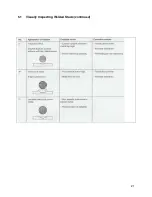
Страница 20: ...20 5 1 Visually Inspecting Welded Studs continued...

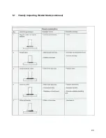
Страница 21: ...21 5 1 Visually Inspecting Welded Studs continued...

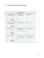
Страница 22: ...22 5 1 Visually Inspecting Welded Studs continued...

Страница 23: ...23 5 1 Visually Inspecting Welded Studs continued...

Страница 24: ...ing parts other than the fan in the power source basic preventive maintenance only involves keeping the welder clean and free from metallic dust Periodically you should ask your Authorized Service Cen...

Страница 25: ...educe duty cycle 1b Make sure that intake and exhaust vents are not blocked In heavy dust areas clean unit out once per month with compressed air B Circuit breaker trips 1 Over voltage or spikes 2 Inc...

Страница 26: ...air 1 Clean surface 2 Read gun manual for procedure 3 Read gun manual for procedure G Display has fluctuating amperage levels H Display is flashing 1 Unit is self calibrating and will complete calibra...

Страница 27: ...of type X to be allowed to be connected between phases and also to comply with the European community CE norms The type X capacitors are connected to a common point making it a virtual neutral This p...

Страница 28: ...ter Design The inverter function is perhaps easiest understood using the simplified block diagram below AC INPUT FIGURE 8 1 RECTIFIER INVERTER MAIN TRANSFORMER RECTIFIER OUTPUT FILTER CONTROL BOARD AU...

Страница 29: ......

Страница 30: ......

Страница 31: ...1 of 1...

Страница 32: ...1 of 1...

Страница 33: ...1 of 1...

Страница 34: ...1 of 1...

Страница 35: ...001 FAN ASSY 15 011216 001 FAN BLADE 17 011220 002 INDUCTOR OUTPUT 18 011230 001 INDUCTOR MAIN w PTC 19 011241 001 INDUCTOR COMMUTATING FRONT 20 011251 001 INDUCTOR COMMUTATING REAR 21 011272 001 TRAN...

Страница 36: ...1 CLAMP OUTPUT CAPACITOR 65 017102 003 CLAMP INPUT CAPACITOR w PTC BOARD 66 017110 001 BRACKET MOUNTING TRANSFORMER 67 018500 001 JACK OUTPUT DINSE FOR PLASTIC PANEL 68 018500 005 JACK OUTPUT DINSE FO...

Страница 37: ...CAMLOCK WA1200 021 EXTENSION CABLE FOR REMOTE 32FT WA1200 031 WORK CLAMP HEAVY DUTY w 10FT 2 0 CABLE CAMLOCK WAP1200 011 CONNECTOR CAMLOCK MALE FOR CABLE WAP1200 012 CONNECTOR CAMLOCK FEMALE FOR CABL...

Отзывы: