


xStack
®
DGS-3600 Series Layer 3 Gigabit Ethernet Managed Switch
level.
Community String or
SNMP V3 User Name
Type in the community string or SNMP V3 user name as appropriate.
To implement your new settings, click
Apply.
To return to the
SNMP Host Table
window, click the
Show All SNMP Host Table
Entries
link.
SNMP Engine ID
The Engine ID is a unique identifier used for SNMP V3
implementations. This is an alphanumeric string used to
identify the SNMP engine on the Switch.
Figure 6- 51. SNMP Engine ID window
To display the Switch's SNMP Engine ID, click
Administration > SNMP Manager > SNMP Engine
ID
, as shown.
To change the Engine ID, enter the new Engine ID in the space provided and click the
Apply
button.
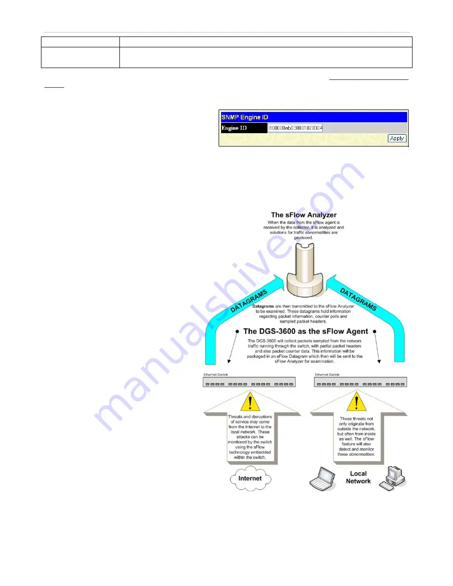
sFlow
sFlow is a feature on the Switch that allows users to
monitor network traffic running through the switch
to identify network problems through packet
sampling and packet counter information of the
Switch. The Switch itself is the sFlow agent where
packet data is retrieved and sent to an sFlow
Analyzer where it can be scrutinized and utilized to
resolve the problem.
The Switch can configure the settings for the sFlow
Analyzer but the remote sFlow Analyzer device must
have an sFlow utility running on it to retrieve and
analyze the data it receives from the sFlow agent.
The Switch itself will collect three types of packet
data:
1.
It will take sample packets from the normal
running traffic of the Switch based on a
sampling interval configured by the user.
2.
The Switch will take a poll of the IF
counters located on the switch.
3.
The Switch will also take a part of the
packet header. The length of the packet
header can also be determined by the user.
Once this information has been gathered by the
switch, it is packaged into a packet called an sFlow
datagram, which is then sent to the sFlow Analyzer
for analysis.
For a better understanding of the sFlow feature of
this Switch, refer to the adjacent diagram.
Figure 6- 52. sFlow Basic Setup
72


