background image


D-Link DMS-1100 Series User Manual


63 

Item 

Description 

Port 

Select the port to be fined. 

Table 4.50 


Click the 

Clear Detected Protocol 

button to clear the detected protocol settings for the port selected.


Click 

Find

 to search the MSTP port information. 

Click the 

Edit 

button to re-configure the specific entry. 


L2 Features > ERPS(G.8032) > ERPS 

ERPS  (Ethernet  Ring  Protection  Switching)  is  the  first  industry  standard  (ITU-T  G.8032)  for  Ethernet  ring 
protection  switching.  It  is  achieved  by  integrating  mature  Ethernet  Operations,  Administration,  and 
Maintenance (OAM)* functions and a simple automatic protection switching (APS) protocol for Ethernet ring 
networks. ERPS provides sub-50ms failover for Ethernet traffic in a ring topology. It ensures that there are no 
loops formed at the Ethernet layer. 
 
One link within a ring, the ring Protection Link (RPL), will be blocked to avoid a Layer 2 loop. When there is a  
failure, protection switching blocks the failed link and unblocks the RPL. When the failure clears, protection 
switching blocks the RPL again and unblocks the link on which the failure is cleared. 


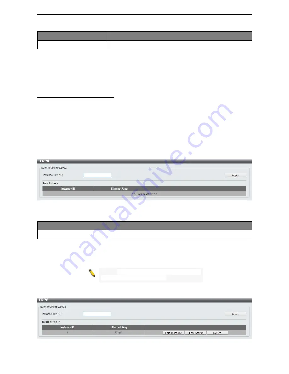
The ERPS page allows user to configure the ERPS instance and profile configuration of the Switch. 


Figure 4.78 – L2 Features > ERPS(G.8032) > ERPS 


The fields that can be configured for

 ERPS 

are described below:


Item 

Description 

Instance ID (1-16) 

Specify the Instance ID to be created. 

Table 4.51 


Click 

Apply

 to make the configurations take effect. 


NOTE: 

STP  and  LBD  should  be  disabled  on  the 

ring ports before enabling ERPS.


Enter

 Instance ID

 1 and click 

Apply

 to create ERPS physical ring. Then the following page will be displayed. 


Figure 4.79 – L2 Features > ERPS(G.8032) > ERPS - Create 

Содержание DMS-1100-10TS

Страница 1: ...User Manual DMS 1100 Series L2 2 5 Gigabit Ethernet Switch Series Rev A 1 ...

Страница 2: ......

Страница 3: ... Supported Web Browsers 13 Connecting to the Switch 13 Login Web based Management 13 Smart Wizard 14 Web based Management 14 4 Configuration 15 Smart Wizard Configuration 15 IPv4 Information 15 SNMP Settings 16 User Accounts Settings 16 Web based Management 17 Tool Bar Save Menu 18 Save Configuration 18 Tool Bar Tool Menu 19 Firmware Information 19 Configuration Information 19 Firmware Upgrade Bac...

Страница 4: ...Zone Settings 35 System Time and SNTP SNTP Settings 37 Management User Accounts Settings 38 Management Password Encryption 39 Management SNMP SNMP Global Settings 39 Management SNMP SNMP View Table Settings 40 Management SNMP SNMP Community Table Settings 41 Management SNMP SNMP Group Table Settings 42 Management SNMP SNMP Engine ID Local Settings 43 Management SNMP SNMP User Table Settings 43 Man...

Страница 5: ...ooping Mrouter Settings 76 L2 Features L2 Multicast Control MLD Snooping MLD Snooping Statistics Settings 77 L2 Features LLDP LLDP Global Settings 78 L2 Features LLDP LLDP Port Settings 79 L2 Features LLDP LLDP Management Address List 80 L2 Features LLDP LLDP Basic TLVs Settings 81 L2 Features LLDP LLDP Dot1 TLVs Settings 82 L2 Features LLDP LLDP Dot3 TLVs Settings 82 L2 Features LLDP LLDP MED Por...

Страница 6: ... Power Saving 104 Green EEE 104 Appendix A Technical Specifications 106 Hardware Specifications 106 Features 108 L2 Features 108 L3 Features 108 VLAN 108 QoS Quality of Service 108 Security 108 OAM 108 Management 108 D Link Green Technology 108 Appendix B Rack mount Instructions 109 ...

Страница 7: ...rs to the DMS 1100 Series switch and switch first letter lower case refers to other Ethernet switches Some technologies use switch bridge and switching hubs interchangeably and all are commonly accepted terms for Ethernet switches A NOTE indicates important information that helps you make better use of the device A CAUTION indicates the potential for property damage or personal injury Copyright an...

Страница 8: ...ve Layer 2 Features Implemented as complete L2 devices these switches include functions such as IGMP snooping port mirroring Spanning Tree ERPS 802 3ad LACP SNTP LLDP and Loopback Detection to enhance performance and network reliability QoS The switches support bandwidth control and 802 1p priority queues enabling users to run bandwidth sensitive applications such as voice and video on the network...

Страница 9: ...een for 2 seconds If the device cannot reboot the Switch the device will enter the loader mode automatically Port Link Act Speed LED 1 8 The port LEDs indicate a network link through the corresponding port Blinking indicates the Switch is either sending or receiving data to the port When the port LED glows amber it indicates the port is running at 100 Mbps or 1000 Mbps When the port LED glows gree...

Страница 10: ...ader mode automatically PoE OK FAIL The PoE LED shows the status of the PoE ports the green light OK indicates that PoE work fine and the amber light Fail indicate that the PoE is working abnormally Port Link Act Speed LED 1 8 The port LEDs indicate a network link through the corresponding port Blinking indicates the Switch is either sending or receiving data to the port When the port LED glows am...

Страница 11: ...curring at any of the ports Solid Amber When there is a secure 100 1000Mbps Ethernet connection or link at any of the ports Blinking Amber When there is reception or transmission i e Activity Act of data occurring at any of the port Light off No link LED Per SFP Port Link Act Speed Green Amber Solid Green When there is a secure 10Gbps connection or link at any of the ports Blinking Green When ther...

Страница 12: ...D Link DMS 1100 Series User Manual 6 Light off No PD device insert ...

Страница 13: ...ching internal components Operate the product only from the type of external power source indicated on the electrical ratings label If you are not sure of the type of power source required consult your service provider or local reseller Also be sure that attached devices are electrically rated to operate with the power available in your location Use only approved power cable s If you have not been...

Страница 14: ...ts contents Please consult the packing list located in the User Manual to make sure all items are present and undamaged One D Link DMS 1100 Series switch One Multilingual Getting Started Guide User Guide CD Power Cord and Power Cord Retainer Rack mount kit and Rubber Feet If any item is found missing or damaged please contact the local reseller for replacement Step 2 Switch Installation For safe s...

Страница 15: ...he mounting brackets to the Switch Then use the screws provided with the equipment rack to mount the switch in the rack Figure 2 3 Mount the Switch in the rack or chassis Step 3 Plugging in the AC Power Cord with Power Cord Clip To prevent accidental removal of the AC power cord it is recommended to install the power cord clip together with the power cord A With the rough side facing down insert t...

Страница 16: ...2 Connect the power cord to the Switch C Slide the Retainer through the Tie Wrap until the end of the cord Figure 2 3 Slide the Retainer through the Tie Wrap D Circle the tie of the Retainer around the power cord and into the locker of the Retainer ...

Страница 17: ... 4 Circle around the power cord E Fasten the tie of the Retainer until the power cord is secured Figure 2 5 Secure the power cord F Users may now connect the AC power cord to an electrical outlet preferably one that is grounded and surge protected ...

Страница 18: ...ired for U S installation Commercially available 6 AWG wire is recommended The length of the cable depends on the proximity of the switch to proper grounding facilities A screwdriver not included in the accessory kit The following steps let you connect the switch to a protective ground Step 1 Verify if the system power is off Step 2 Use the ground cable to place the 8 terminal lug ring on top of t...

Страница 19: ...er a successful physical installation you can configure the Switch monitor the network status and display statistics using a web browser Supported Web Browsers The embedded Web based Management currently supports the following web browsers Internet Explorer 7 or later version Chrome Firefox Safari Connecting to the Switch You will need the following equipment to begin the web configuration of your...

Страница 20: ...rface then click OK The switch supports 10 languages including English Traditional Chinese Simplified Chinese German Spanish French Italian Portuguese Japanese and Russian By default the language is English Enter the User name and Password with admin and press Login to enter the main configuration window Figure 3 3 Login Dialog Box Smart Wizard After a successful login the Smart Wizard will guide ...

Страница 21: ...wizard next time for the next time you logon to the Web based Management IPv4 Information IPv4 Information will guide you to do basic configurations on 3 steps for the IP Information access password and SNMP Select Static to manually enter a new IP Address Netmask and Gateway address or select DHCP to automatically receive IP settings from a DHCP server Click the Next button to enter the SNMP sett...

Страница 22: ... SNMP function The default SNMP Setting is Disabled Click Enabled and then click Next then it will enter the User Accounts Settings page Figure 4 2 SNMP Settings in Smart Wizard User Accounts Settings The User Accounts Settings page allows user to quickly specify the user account function Enter the User Name Privilege Password Type and Password Click Apply Save to save the configuration ...

Страница 23: ...S 1100 Series User Manual 17 Figure 4 3 User Accounts Setting in Smart Wizard Web based Management After clicking the Exit button in the Smart Wizard you will see the screen below Figure 4 4 Web based Management ...

Страница 24: ...s the Logout button Click this to end this session NOTE If you close the web browser without clicking the Logout button first then it will be seen as an abnormal exit and the login session will still be occupied Click the D Link logo at the upper left corner of the screen to be redirected to the local D Link website Tool Bar Save Menu The Save Menu provides Save Configuration and Save Log function...

Страница 25: ...has been booted and the image that is selected for the next reboot Figure 4 8 Tool Menu Firmware Information Configuration Information The Configuration Information page displays information for the Switch configuration This includes the configuration that has been loaded and the configuration that is selected for the next reboot Figure 4 9 Tool Menu Configuration Information Firmware Upgrade Back...

Страница 26: ...his Firmware Upgrade from TFTP page allows user to upgrade firmware using TFTP Figure 4 11 Tool Menu Firmware Upgrade Backup Firmware Upgrade from TFTP The fields that can be configured for Firmware Upgrade from TFTP are described below Item Description TFTP Server IP Select IPv4 or IPv6 and enter the address to be configured Source URL Enter the source URL address Destination URL Displays the des...

Страница 27: ...ckup to TFTP The fields that can be configured for Firmware Backup to TFTP are described below Item Description TFTP Server IP Select IPv4 or IPv6 and enter the address to be configured Source Enter the source URL address Destination URL Displays the destination URL address Table 4 5 Click the Upgrade button to upgrade the firmware to specified TFTP address Configuration Upgrade Backup Configurati...

Страница 28: ... Description TFTP Server IP Select IPv4 or IPv6 and enter the address to be configured Destination URL Displays the destination URL address Startup config Check the box to enable the startup configuration function Source URL Enter the source URL address Table 4 7 Click the Restore button to upgrade the configuration from specified TFTP address Configuration Upgrade Backup Configuration Backup to H...

Страница 29: ...kup to HTTP The Log Backup to HTTP page allows user to save the log to a file Figure 4 18 Tool Menu Log Backup Log Backup to HTTP Log Backup Log Backup to TFTP The Log Backup to TFTP page allows user to save the log to a file using TFTP Figure 4 19 Tool Menu Log Backup Log Backup to TFTP The fields that can be configured for Log Backup are described below Item Description TFTP Server IP Select IPv...

Страница 30: ...is from 1 to 99 seconds IPv6 Ping Target Ipv6 Address Enter the IPv6 address to be pinged Ping Times 1 255 Specify the ping time The range is from 1 to 255 Timeout 1 99 Specify the timeout period while waiting for a response from the remote device The range is from 1 to 99 seconds Table 4 10 Click Apply to make the configurations take effect Reset Select which reset option you want to perform and ...

Страница 31: ...ig 1 location Table 4 11 Click Reboot to reboot the system with specified configuration Tool Bar Smart Wizard By clicking the Smart Wizard button you can re run to the Smart Wizard if you wish to make any changes Tool Bar Online Help The Online Help provides two ways of online support D link Support Site will lead you to the D Link website where you can find online resources such as updated firmwa...

Страница 32: ...D Link DMS 1100 Series User Manual 26 Figure 4 24 User Guide Micro Site ...

Страница 33: ...igure The following sections provide more detailed description of each feature and function Figure 4 25 Function Tree Device Information The Device Information provides an overview of the switch including essential information such as firmware hardware information and IP settings Figure 4 26 Device Information System System Information The System Setting page allows user to configure basic system ...

Страница 34: ... can be monitored and adjusted for optimum configuration Figure 4 28 System Port Configuration Port Settings The fields that can be configured for Port Settings are described below Item Description From Port To Port Select the appropriate port range to be configured Media Select the media type for specified port The media type is Copper for port 1 port 8 and Fiber for port 9 port 10 State Enable o...

Страница 35: ...d can be selected with 1000M and 10G Description Enter a 64 characters description for the corresponding port Table 4 13 Click Apply to make the configurations take effect Click the Refresh button to refresh the displayed table System Port Configuration Port Status The Port Settings page allows user to view the Switch s physical port status and settings The table will display the Port Status MAC A...

Страница 36: ... Specify the error disable causes Options to choose from are Storm and Loopback Detect State Select to enable or disable the auto recovery for an error port caused by the specified cause Interval 5 586400 Enter the time interval The values are between 5 and 586400 seconds And default value is 300 Table 4 14 Click Apply to make the configurations take effect System Port Configuration Jumbo Frame Th...

Страница 37: ...SE Maximum Power Levels at the Powered Device 0 Default 15 4W 0 44 to 12 95W 1 Optional 4 0W 0 44 to 3 84W 2 Optional 7 0W 3 84 to 6 49W 3 Optional 15 4W 6 49 to 12 95W 4 Optional Treat as Class 0 Reserved for future use IEEE 802 3at defined that the PSE provides power according to the following classification Class Usage Powered Device Classification Guaranteed output power by PSE Output Maximum ...

Страница 38: ...E Status DMS 1100 10TP only The PoE Status page displays the PoE status of each port Figure 4 33 System PoE PoE Status Note For the PoE Port Settings table if the classification was shown as Legacy PD it will be classified to non AF PD or Legacy PD System PoE PoE Configuration DMS 1100 10TP only The PoE Configuration page is used to configure the PoE port Figure 4 34 System PoE PoE Configuration T...

Страница 39: ...etermines the maximum wattage which can be provisioned The valid range for maximum wattage is between 1000 mW and 30000 mW Table 4 17 Click Apply to make the configurations take effect Note For DMS 1100 10TP the port 1 port 8 are compliance with 802 3at The total PoE budget is 240 Watts System PoE PoE Measurement DMS 1100 10TP only The PoE measurement page displays the measurement information of P...

Страница 40: ... feature Table 4 18 Click Apply to make the configurations take effect System System Log System Log Server Settings The System Log Server Settings page allows user to view and configure the system log s server settings Figure 4 37 System System Log System Log Server Settings The fields that can be configured for System Log Server Settings are described below Item Description IPv4 Address Select an...

Страница 41: ...ure 4 39 System Time and SNTP Clock Settings The fields that can be configured for Clock Settings are described below Item Description Time HH MM SS Enter the current time in hours minutes and seconds Data DD MM YYYY Enter the current day month and year to update the system clock Table 4 20 Click Apply to make the configurations take effect System Time and SNTP Time Zone Settings The Time Zone Set...

Страница 42: ...ing time will start From Day of the Week Select day of the week that daylight saving time will start From Month Select the month that daylight time will start From Time in HH MM Select the time of the day that daylight saving time will start To Week of the Month Select week of the month that daylight saving time will end To Day of the Week Specify day of the week that daylight saving time will end...

Страница 43: ...et Select the number of minutes to add during daylight saving time The default value is 60 The range of this offset is 30 60 90 and 120 Table 4 21 Click Apply to make the configurations take effect System Time and SNTP SNTP Settings The SNTP Settings page allows user to configure the time settings for the Switch Figure 4 41 System Time and SNTP SNTP Settings The fields that can be configured for S...

Страница 44: ... Privilege Level 15 This administrator user account level can monitor all system information and change any of the system configuration settings expressed in this guide Figure 4 42 Management User Accounts Settings The fields that can be configured for User Accounts Settings are described below Item Description User Name Enter the name of the user name The name can be up to 32 characters long Priv...

Страница 45: ...ettings of gateways routers switches and other network devices Use SNMP to configure system features for proper operation monitor performance and detect potential problems on the Switch or your local network Managed devices that support SNMP include software referred to as an agent which runs locally on the device A defined set of variables managed objects is maintained by the SNMP agent and used ...

Страница 46: ...are formed with an incorrect community string For SNMPv3 authentication failure occurs if packets are formed with an incorrect SHA MD5 authentication key Port Link Up Check this feature to enable Link Up traps Whenever a device changes status from link down to link up it will send a Link Up trap to the management station Port Link Down Check this feature to enable Link Down traps Whenever a device...

Страница 47: ...d or excluded from access by an SNMP manager View Type Select the OIDs that can accessed by a SNMP manager Table 4 26 Click Add to create a new view or Delete to remove an existing view Management SNMP SNMP Community Table Settings The SNMP Community page allows user to set the SNMP community string of the Switch SNMP managers using the same community string are permitted access to the Switch s SN...

Страница 48: ...the MIBs on the Switch Read Write SNMP community members can read and write the contents of the MIBs on the Switch Table 4 27 Click Add to a new entry based on the information entered or Delete to remove the specified entry Management SNMP SNMP Group Table Settings The SNMP Group page allows user to manage SNMP Groups Access to SNMP OIDs and security policies can be controlled on a per group basis...

Страница 49: ...P group name for users that are allowed SNMP write privileges to the Switch s SNMP agent Notify View Name Enter a SNMP group name for users that can receive SNMP trap messages generated by the Switch s SNMP agent Table 4 28 Click the Add button to add a new entry based on the information entered Click the Delete button to remove the specified entry Management SNMP SNMP Engine ID Local Settings The...

Страница 50: ...AC SHA authentication protocol will be used This field will require the user to enter a password Priv Protocol by Password Select either None or DES56 and then enter a password for SNMPv3 encryption in the right column None Select to not use any authorization DES56 Select to use DES 56 bit encryption based on the CBC DES DES 56 standard This field will require you to enter a password Auth Protocol...

Страница 51: ...n selecting SNMPv3 in the User based Security Model drop down list this option is available NoAuthNoPriv Select to have no authorization and no encryption of packets sent between the Switch and a remote SNMP manager AuthNoPriv Select to require authorization but with no encryption of packets sent between the Switch and a remote SNMP manager AuthPriv Select to require authorization and packets sent...

Страница 52: ...s user to configure the session timeout on the Switch Figure 4 53 Management Session Timeout The fields that can be configured for Session Timeout are described below Item Description Web Session Timeout 60 36000 Enter the time in seconds of the web session timeout The range of timeout is between 60 and 36000 seconds Tick the Default check box to use default value The default is 180 Table 4 32 Cli...

Страница 53: ...20 and Never DDP Port Settings From Port To Port Enter the appropriate port range used for the configuration State Select to enable or disable the DDP port state Table 4 33 Click Apply to make the configurations take effect L2 Features FDB Static FDB Unicast Static FDB The Unicast Static FDB page allows user to view and configure the static unicast forwarding settings on the Switch Figure 4 55 L2 ...

Страница 54: ...C address Table 4 34 Click Apply to make the configurations take effect Click the Delete All button to delete all the entries found in the display table Enter a page number and click the Go button to navigate to a specific page when multiple pages exist L2 Features FDB Static FDB Multicast Static FDB The Multicast Static FDB page allows user to view and configure the static multicast forwarding se...

Страница 55: ...tem Description Aging Time Enter the MAC address table s aging time value This value must be between 10 and 410 seconds Entering 0 will disable MAC address aging By default this value is 300 seconds Aging Destination Hit Select to enable or disable the aging destination hit function Table 4 36 Click Apply to make the configurations take effect After clicking the MAC Address Learning tab the follow...

Страница 56: ...figuration Table 4 38 Click the Find button to locate a specific entry based on the information entered Click the Clear Dynamic by Port button to clear the dynamic MAC address listed on the corresponding port Click the Clear Dynamic by VLAN button to clear the dynamic MAC address listed on the corresponding VLAN Click the Clear Dynamic by MAC button to clear the dynamic MAC address entered Click t...

Страница 57: ...it button to re configure the specific entry Enter a page number and click the Go button to navigate to a specific page when multiple pages exist L2 Features Asymmetric VLAN The Asymmetric VLAN page allows user to configure the asymmetric VLAN function on this switch Figure 4 61 L2 Features Asymmetric VLAN The fields that can be configured for MAC Address Table are described below Item Description...

Страница 58: ...ce VLAN Detail The fields that can be configured for VLAN Interface are described below Item Description Port Display the VLAN port number VLAN Mode Select the VLAN mode option Options to choose from are Access Hybrid and Trunk Acceptable Frame Type Select the acceptable frame type behavior option Options to choose from are Tagged Only Untagged Only and Admit All Ingress Checking Select to enable ...

Страница 59: ...he ports surveillance VLAN information Figure 4 65 L2 Features Auto Surveillance VLAN Auto Surveillance Properties The fields that can be configured for Auto Surveillance Properties are described below Item Description Global Settings Surveillance VLAN Specify to enable or disable the surveillance VLAN state Surveillance VLAN ID Enter the surveillance VLAN ID The range is from 1 to 4094 Surveillan...

Страница 60: ...ngs and Surveillance Device page is used to configure the user defined surveillance device OUI and display the surveillance VLAN information Figure 4 66 L2 Features Auto Surveillance VLAN MAC Settings and Surveillance Device The fields that can be configured for MAC Settings and Surveillance Device are described below Item Description Component Type Specify the surveillance component type Option t...

Страница 61: ...be configured for Voice VLAN Global Settings are described below Item Description Voice VLAN State Select to enable or disable Voice VLAN VLAN ID 1 4094 Enter the voice VLAN ID The value is range from 1 to 4094 Voice VLAN CoS Specify the priority of the voice VLAN from 0 to 7 Aging Time Enter the aging time of surveillance VLAN The range is from 1 to 65535 minutes The default value is 720 minutes ...

Страница 62: ...from are Auto Untagged Auto Tagged and Manual Table 4 45 Click the Apply button to accept the changes made L2 Features Voice VLAN Voice VLAN OUI The Voice VLAN OUI page is used to configure the user defined voice traffic s OUI The OUI is used to identify voice traffic There are a number of pre defined OUIs The user can further define the user defined OUIs if needed The user defined OUI cannot be t...

Страница 63: ...s of the Spanning Tree Protocol Rapid Spanning Tree Protocol RSTP as defined by IEEE 802 1w a version compatible with the IEEE 802 1D STP and Multiple Spanning Tree Protocol MSTP as defined by IEEE802 1 RSTP can operate with legacy equipment implementing IEEE 802 1D however the advantages of using RSTP will be lost The Rapid Spanning Tree Protocol RSTP evolved from the 802 1D STP standard and was ...

Страница 64: ...L2 Features STP STP Global Settings The fields that can be configured for STP Global Settings are described below Item Description STP State STP State Select to enable or disable the Spanning Tree Protocol STP Traps STP New Root Trap Select to enable or disable the STP new root trap option STP Topology Change Trap Select to enable or disable the STP topology change trap option STP Mode STP Mode Se...

Страница 65: ...s the interval between two transmissions of BPDU packets sent by the Root Bridge to all switches This field will only appear when STP or RSTP is selected for the STP Version For MSTP the Hello Time must be set on a port by port basis TX Hop Count 1 10 Enter the transmit hold count value This value must be between 1 and 10 The default value is 6 This value is used to set the maximum number of Hello...

Страница 66: ... cost The lower the number the greater the probability the port will be chosen to forward packets State Select to enable or disable port based STP It will be selectable after STP is enabled globally on the Switch Guard Root Select to enable or disable the guard root function Link Type Select the link type option The options to choose from are Auto P2P and Shared A full duplex port is considered to...

Страница 67: ... is 128 The lower the number the greater the probability the port will be chosen as a root port Hello Time The interval between two transmissions of BPDU packets sent by the Root Bridge to indicate to all other switches that it is indeed the Root Bridge The default value is 2 Table 4 48 Click Apply to make the configurations take effect L2 Features STP MST Configuration Identification Multiple Spa...

Страница 68: ...hat the edit type is removed VID List Enter the VID range from configured VLANs set on the Switch Table 4 49 Click Apply to define the configuration name and revision level Click the Edit to modify the setting of VID or click Delete to remove it L2 Features STP STP Instance The STP Instance Settings page display MSTIs currently set on the Switch and allows users to change the Priority of the MSTPs...

Страница 69: ...ures that there are no loops formed at the Ethernet layer One link within a ring the ring Protection Link RPL will be blocked to avoid a Layer 2 loop When there is a failure protection switching blocks the failed link and unblocks the RPL When the failure clears protection switching blocks the RPL again and unblocks the link on which the failure is cleared The ERPS page allows user to configure th...

Страница 70: ...d Port1 Specifies the port as the second ring port and also specifies the virtual port channel used Description Enter the description for the specified instance R APS Channel VLAN 1 4094 Specifies the R APS channel of ERP instance The range is between 1 and 4094 Inclusion VLAN List Specifies to add or delete the inclusion VLAN group The VLANs specified here will be protected by the ERP mechanism M...

Страница 71: ...witch Figure 4 82 L2 Features ERPS G 8032 ERPS Profile The fields that can be configured for ERPS Profile are described below Item Description Profile Name Specify the profile name to be created on the Switch Table 4 53 Click Apply to make the configurations take effect Click the Delete button to remove the profile Enter Profile Name and click Apply button to associate the G 8032 profile with the ...

Страница 72: ...ault hold off time is 0 milliseconds WTR Timer 1 12 Specifies the WTR time of the R APS function The value is between 1 and 12 minutes The default WTR time is 5 minutes Table 4 54 Click Apply to make the configurations take effect Click the Back button to return to the previous page L2 Features Loopback Detection The Loopback Detection function is used to detect the loop created by a specific port...

Страница 73: ...s selected in the Mode drop down list Interval 1 32767 Set a Loop Detection Interval between 1 and 32767 seconds The default is 2 seconds Trap State Select to enable or disable the loopback detection trap state Action Select Shut down or None for loopback detection Loopback Detection Port Settings From Port To Port Enter a consecutive group of ports to be configured starting with the selected port...

Страница 74: ...rmation Channel Group Information From Port To Port Select the appropriate port range used for the configuration Group ID Enter the channel group number This value must be between 1 and 32 The system will automatically create the port channel when a physical port first joins a channel group An interface can only join one channel group Mode Select either On Active or Passive If you selected On the ...

Страница 75: ...that can be configured for IGMP Snooping Settings are described below Item Description Global Settings Global State Select to enable or disable the IGMP Snooping global state VLAN Status Settings VID 1 4094 Enter the VLAN ID and select to enable or disable the IGMP snooping on the VLAN IGMP Snooping Table VID 1 4094 Enter the VLAN ID between 1 and 4094 Table 4 57 Click Apply to make the configurat...

Страница 76: ...sable the IGMP snooping fast leave function Querier State Select to enable or disable the querier state Query Version Select the general query packet version sent by the IGMP snooping querier Query Interval 1 31744 Enter the interval at which the IGMP snooping querier sends IGMP general query messages periodically Max Response Time 1 25 Enter the interval at which the IGMP snooping querier sends I...

Страница 77: ... VID 1 4094 Enter the VLAN ID Group Address Enter the IP multicast group address From Port To Port Select the range of ports to be configured Table 4 59 Click Apply to make the configurations take effect Click the Delete button to remove the specified entry Click the Find button to locate a specific entry based on the information entered Click the Find All button to view all the entries Enter a pa...

Страница 78: ...cast router port Forbidden Port Select to configure the port as a port that cannot be a static multicast router port From Port To Port Select the range of ports to be configured Table 4 61 Click Apply to make the configurations take effect Click the Delete button to remove the specified entry The fields that can be configured for IGMP Snooping Mrouter Table are displayed below Item Description VID...

Страница 79: ...ng related statistics The fields that can be configured for IGMP Snooping Statistics Table are displayed below Item Description Find Type Select the interface to be searched The options are VLAN and Port VID 1 4094 Enter the VLAN ID Table 4 64 Click the Find button to locate a specific entry based on the information entered Click the Find All button to view all the entries L2 Features L2 Multicast...

Страница 80: ...e Find button to locate a specific entry based on the information entered Click the Find All button to view all the entries Click the Show Detail button to see the detail information of the specific VLAN Click the Edit button to re configure the specific entry After clicking the Show Detail button the following window will appear Figure 4 94 L2 Features L2 Multicast Control MLD Snooping MLD Snoopi...

Страница 81: ...ch the MLD snooping querier sends MLD general query messages periodically Max Response Time 1 25 Enter the maximum response time in seconds advertised in MLD snooping queries The range is 1 to 25 Robustness Value 1 7 Enter the robustness variable used in MLD snooping Last Member Query Interval 1 25 Enter the interval at which the MLD snooping querier sends MLD group specific or group source specif...

Страница 82: ...ind All button to view all the entries Enter a page number and click the Go button to navigate to a specific page when multiple pages exist The fields that can be configured for the MLD Snooping Groups Table are described below Item Description VID 1 4094 Enter the VLAN ID Group Address Enter the IP multicast group address From Port To Port Select the range of ports to be configured Table 4 68 Cli...

Страница 83: ... configurations take effect Click the Delete button to remove the specified entry Click the Find button to locate a specific entry based on the information entered Click the Find All button to view all the entries Enter a page number and click the Go button to navigate to a specific page when multiple pages exist L2 Features L2 Multicast Control MLD Snooping MLD Snooping Statistics Settings The ML...

Страница 84: ...e displayed Table 4 71 Click the Find button to locate a specific entry based on the information entered Click the Find All button to view all the entries L2 Features LLDP LLDP Global Settings Link Layer Discovery Protocol LLDP is and IEEE 802 1AB standards compliant method for switches to advertise themselves to neighbor devices as well as to learn about neighbor LLDP devices SNMP utilities can l...

Страница 85: ... the interval at which LLDP frames are transmitted on behalf of this LLDP agent The default value is 30 seconds Message TX Hold Multiplier 2 10 This parameter is a multiplier that determines the actual TTL value used in an LLDPDU The default value is 4 LLDP ReInit Delay 1 10 This parameter indicates the amount of delay from the time adminStatus becomes disabled until re initialization is attempted...

Страница 86: ...itting LLDP packets only RX Enables receiving LLDP packets only TX and RX Enables transmitting and receiving LLDP packets This is the default value Disabled Disables LLDP on the port IP Subtype Select the type of the IP address information to be sent Options to choose from are All IPv4 and IPv6 Action Select to remove or add the action field Address Enter the IP address to be sent Table 4 73 Click...

Страница 87: ...page allows user to configure the LLDP Port settings Figure 4 102 L2 Features LLDP LLDP Basic TLVs Settings The fields that can be configured for the LLDP Basic TLVs Settings are described below Item Description From Port To Port Select the range of ports to be configured Port Description Select to enable or disable the Port Description option System Name Select the system name to be enabled or di...

Страница 88: ... VLAN bridge port to advertise the port s VLAN identifier PVID that will be associated with untagged or priority tagged frames Protocol VLAN Select to enable or disable Port and Protocol VLAN ID PPVID TLV to send and enter the VLAN ID in PPVID TLV VLAN Name Select to enable or disable the VLAN name TLV to send and enter the ID of the VLAN in the VLAN name TLV Protocol Identity Select to enable or ...

Страница 89: ... Aggregation Specifies whether the link aggregation is enabled on the port The possible field values are Enabled Enables the link aggregation configured on the port Disabled Disables the link aggregation configured on the port Maximum Frame Size Specifies whether the link aggregation is enabled on the port The possible field values are Enabled Enables the Maximum Frame Size configured on the port ...

Страница 90: ...ription From Port To Port Select the range of ports to be configured Capabilities Select to enable or disable transmitting the LLDP MED capabilities TLV Network Policy Select to enable or disable transmitting the LLDP MED network policy TLV Inventory Select to enable or disable transmitting the LLDP MED inventory management TLV Table 4 78 Click Apply to make the configurations take effect L2 Featu...

Страница 91: ...ue to the Time To Live expiring Table 4 79 Click the Clear Counter button to clear the counter information for the statistics displayed The fields that can be displayed for the LLDP port Statistics are described below Item Description Port Select the port to be displayed Total Transmits Displays the total number of LLDP frames transmitted on the port Total Discards Displays the total discarded fra...

Страница 92: ... information displayed L2 Features LLDP LLDP Local Port Information The LLDP Local Port Information page displays LLDP local port information Figure 4 107 L2 Features LLDP LLDP Local Port Information The fields that can be displayed for the LLDP Local Port information are described below Item Description Port Displays the port number Port ID Subtype Displays the port ID subtype Port ID Displays th...

Страница 93: ...ormation Click the Find button to locate a specific entry based on the information entered Click the Clear button to remove the specified port of LLDP neighbor port or click Clear All button to remove all LLDP neighbor ports L3 Features IPv4 Interface The IPv4 Interface page allows displays the information of IPv4 Interface entries Figure 4 110 L3 Features IPv4 Interface Click the Edit button to r...

Страница 94: ...network IP Address Enter the IPv4 Address for this interface Mask Enter the IPv4 subnet mask for this interface Table 4 82 Click the Back button to return to the previous window Click Apply to make the configurations take effect After clicking the DHCP Client tab the following page will appear Figure 4 112 L3 Features IPv4 Interface DHCP Client The fields that can be configured for the DHCP Client...

Страница 95: ...e the IPv4 default gateway settings Figure 4 113 L3 Features IPv4 Default Gateway The fields that can be configured for the IPv4 Default Gateway are described below Item Description Gateway Enter the gateway address for IPv4 route If this is a default route then this is the default gateway Table 4 84 Click Apply button to accept the changes made Click the Delete button to remove the specific entry...

Страница 96: ... the EUI 64 interface ID Select the Link Local option to configure a link local address for the IPv6 interface NS Interval Settings NS Interval 1 3600 Specify the NS interval and the values are between 1 and 3600 Table 4 85 Click Apply to make the configurations take effect After clicking the Interface IPv6 Address tab located at the top of the page the following page will appear Figure 4 116 L3 F...

Страница 97: ... CoS settings Figure 4 118 QoS Port Default CoS The fields that can be configured for the Port Default Cos are described below Item Description From Port To Port Select the range of ports to be configured Default CoS Select the default CoS option for the specified ports The values are from 0 to 7 Click the Override check box to apply the port s default CoS to all packets tagged or untagged receive...

Страница 98: ...e Strict Priority SP and Weighted Round Robin WRR By default the output queue scheduling algorithm is SP Table 4 88 Click Apply to make the configurations take effect QoS Queue Settings The Queue Settings page allows user to configure the queue settings Figure 4 120 QoS Queue Settings The fields that can be configured for the Queue Settings are described below Item Description Queue ID Select the ...

Страница 99: ...escribed below Item Description Queue ID Select the queue ID that will be mapped to the corresponding CoS value The value is from are 0 to 7 Table 4 90 Click Apply to make the configurations take effect QoS Port Rate Limiting The Port Rate Limiting page allows user to view and configure the port rate limiting settings Figure 4 122 QoS Port Rate Limiting The fields that can be configured for the Po...

Страница 100: ...bytes Select the None option to remove the rate limit on the specified port s The specified limitation cannot exceed the maximum speed of the specified interface For the ingress bandwidth limitation the ingress can trigger a pause frame or a flow control frame when the received traffic exceeds the limitation Table 4 91 Click Apply to make the configurations take effect Security Safeguard Engine D ...

Страница 101: ...milar to using VLANs to limit traffic but is more restrictive Figure 4 125 Security Traffic Segmentation Settings The fields that can be configured for the Traffic Segmentation Settings are described below Item Description From Port To Port Select the range of ports to be configured From Forward Port To Forward Port Select the range of forward ports to be configured Table 4 93 Click the Add button...

Страница 102: ... notification will be sent when a storm event is cleared Storm Control Trap Polling Settings Interval 1 300 Enter the interval value The range is from 1 to 300 Retries 0 360 Enter the retry value The range is from 0 to 360 Storm Control Port Settings From Port To Port Select the range of ports to be configured Type Select the type of storm attack The values are Broadcast Multicast and Unicast Acti...

Страница 103: ...eath Attack and All Types DoS Settings State Select to enable or disable the DoS attack prevention state Action Select the action for the DoS attack Table 4 95 Click Apply to make the configurations take effect Security SSL SSL Global Setting Secure Sockets Layer SSL is a security feature that provides a secure communication path between the management PC and the Switch Web UI by using authenticat...

Страница 104: ...cy The SSL Service Policy page allows user to view and configure the SSL service policy settings Figure 4 129 Security SSL SSL Service Policy The fields that can be configured for SSL Service Policy are described below Item Description Policy Name Enter a policy name for SSL Session Cache Timeout 60 86400 Enter the session cache timeout value The value is between 60 and 86400 seconds Cipher Suites...

Страница 105: ... start the diagnosis Figure 4 130 OAM Cable Diagnostic Click the Clear button to clear all the information for the specific port Click the Clear All button to clear all the information in this table NOTE Please be sure that the Power Saving feature is disabled before enabling the Cable Diagnostics function Monitoring Statistics Port This Port page allows user to display the port traffic statistics...

Страница 106: ...on entered Click the Refresh button to refresh the display table After clicking the Show Detail button the following page will appear Figure 4 132 Monitoring Statistics Port Show Detail Click the Back button to return to the previous window Click the Refresh button to refresh the display table Monitoring Statistics Port Counters The Port Counters page allows user to display port counter statistics...

Страница 107: ...ick the Find button to locate a specific entry based on the information entered Click the Refresh button to refresh the display table Click the Show Errors button to see all error counters of the specific port After clicking the Show Errors button the following page will appear Figure 4 134 Monitoring Statistics Port Counters Show Errors Click the Back button to return to the previous window Click...

Страница 108: ...cription From Port To Port Select the range of ports to be viewed Table 4 100 Click the Find button to locate a specific entry based on the information entered Click the Refresh button to refresh the display table Click the Clear button to clear all the information for the specific ports Click the Clear All button to clear all the information in this table Click the Show Detail button to see the d...

Страница 109: ...fresh button to refresh the display table Monitoring Mirror Settings The Mirror Settings page allows user to view and configure the port mirroring feature Figure 4 137 Monitoring Mirror Settings The fields that can be configured for Mirror Settings are described below Item Description Mirror Settings Session Number Select the mirror session number for the entry ...

Страница 110: ...pecific entry based on the information entered Green Power Saving The Power Saving page allows user to configure the power saving settings of the Switch Figure 4 138 Green Power Saving The fields that can be configured for Power Saving are described below Item Description Administrative Dim LED Select to enable or disable the scheduled port shutdown power saving feature Table 4 102 Click Apply to ...

Страница 111: ...0 Series User Manual 105 Item Description From Port To Port Select the range of ports to be configured State Select to enable or disable the EEE feature Table 4 103 Click Apply to make the configurations take effect ...

Страница 112: ...00 1000 2 5GBASE T Ethernet Ports DMS 1100 10TS 8 x 10 100 1000 2 5GBASE T ports DMS 1100 10TP 8 x 10 100 1000 2 5GBASE T ports 1000Base T ports compliant to following standards IEEE 802 3 compliance IEEE 802 3u compliance IEEE 802 3ab compliance IEEE 802 3bz compliance Support Half Full Duplex operations IEEE 802 3x Flow Control support for Full Duplex mode Back Pressure for Half Duplex mode Head...

Страница 113: ...ion 293 4 Watts PoE on 38 1 Watts PoE Off Standby power consumption 27 3 Watts Power Supply AC input 100 240 VAC 50 60Hz internal universal power supply Fans DMS 1100 10TS 1 Smart Fan DMS 1100 10TP 3 Smart Fans Operating Temperature 5 50 C Storage Temperature 40 70 C Humidity Storage 0 95 non condensing Dimensions DMS 1100 10TS 440mm x 210mm x 44mm DMS 1100 10TP 440mm x 250mm x 44mm Weight DMS 110...

Страница 114: ...rity Trusted Host Traffic Segmentation D Link Safeguard Engine Broadcast Storm Control SSL Support v1 v2 OAM Cable Diagnostics Reset button reset to factory default Management Web based GUI SNMP support DHCP client Trap setting for destination IP system events fiber port events twisted pair port events Password access control Web based configuration backup restoration Web based firmware backup res...

Страница 115: ...lation of the equipment in a rack should be such that the amount of air flow required for safe operation of the equipment is not compromised C Mechanical Loading Mounting of the equipment in the rack should be such that a hazardous condition is not achieved due to uneven mechanical loading D Circuit Overloading Consideration should be given to the connection of the equipment to the supply circuit ...

Страница 116: ...110 ...

Отзывы: