background image

D-Link DES-3350SR Standalone Layer 3 Switch 

145 

Layer 3 Features 

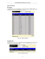
IP Address 

The 

IP Address


Table

 may be found in the 

Monitoring

 menu in the 

Layer 3 Feature

 folder. The 

IP Address


Table

 is a read 

only screen where the user may view IP addresses discovered by the Switch. To search a specific IP address, enter it into the field 
labeled 

IP Address

 at the top of the screen and click 

Find

 to begin your search. 


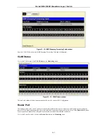
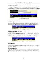
Figure 10 - 23. IP Address Routing Table  


Routing Table 

The 

Routing Table

 window may be found in the 

Monitoring

 menu in the 

Layer 3 Feature

 folder. This screen shows the current 

IP routing table of the Switch. To find a specific IP route, enter an IP address into the 

Destination Address

 field along with a 

proper subnet mask into the 

Mask

 field and click 

Find


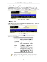
Figure 10 - 24. Routing Table window 

Содержание DES-3350SR

Страница 1: ...D Link DES 3350SR Standalone Layer 3 Switch User s Guide...

Страница 2: ...ion is strictly forbidden Trademarks used in this text D Link and the D Link logo are trademarks of D Link Computer Corporation Microsoft and Windows are registered trademarks of Microsoft Corporation...

Страница 3: ...king 3 Routing Protocol 3 Security 3 Access Control List support ACL 3 Unpacking and Setup 5 Unpacking 5 Installation 5 Desktop or Shelf Installation 5 Rack Installation 5 Power on 6 Power Failure 6 I...

Страница 4: ...cast Forwarding 34 VLANs 35 Static VLAN Entry 36 Port VLAN ID PVID 38 Port Bandwidth 41 SNTP Settings 42 Current Time Settings 43 Time Zone and DST 43 Port Security 44 QOS Quality of Service 46 Traffi...

Страница 5: ...OSPF Host Route Settings 119 DHCP BOOTP Relay 120 DHCP BOOTP Relay Information 120 DHCP BOOTP Relay Interface Settings 121 DNS Relay 121 DNS Relay Information 122 DNS Relay Static Settings 122 IP Mult...

Страница 6: ...PIM Monitoring 149 PIM Neighbor Table 149 Maintenance 151 TFTP Utilities 151 Download Firmware from Server 151 Download Settings from TFTP Server 151 Upload Settings to TFTP Server 151 Upload Log to T...

Страница 7: ...Profile Table Port Mirroring and configuring the Spanning Tree Section 8 Management A detailed discussion regarding the Simple Network Management Protocol including description of features and a brief...

Страница 8: ...switch if provided on the power supply is set to match the power available at your location 115 volts V 60 hertz Hz in most of North and South America and some Far Eastern countries such as South Kore...

Страница 9: ...e before extending a component from the rack Use caution when pressing the component rail release latches and sliding a component into or out of a rack the slide rails can pinch your fingers After a c...

Страница 10: ...e ready to install the component in your system Just before unwrapping the antistatic packaging be sure to discharge static electricity from your body 2 When transporting a sensitive component first p...

Страница 11: ...segments which are not competing with each other for network transmission capacity and therefore decreasing the load on each segment The Switch acts as a high speed selective bridge between the indivi...

Страница 12: ...ssification based on MAC SA DA Spanning Tree 802 1D Spanning tree compatible 802 1w Rapid Spanning Tree support VLAN 802 1Q support GARP GVRP Number of VLANs supported per device IP Multicast IGMP Sno...

Страница 13: ...ON RFC 1643 Ether like MIB Private MIB IGMP MIB 802 1p RFC2674 RFC 2233 Evolution of the Interfaces Group of MIB II Receive Address Group is not supported RIP MIB OSPF RFC1850 CIDR MIB RFC2096 RMON 4...

Страница 14: ...D Link DES 3350SR Standalone Layer 3 Switch 4 Based on VLAN Based on IP address Based on TCP UDP port number Based on 802 1p priority Based on DSCP...

Страница 15: ...power outlet should be within 1 82 meters 6 feet of the device Visually inspect the power cord and see that it is secured to the AC power connector Make sure that there is proper heat dissipation from...

Страница 16: ...ource automatically and may be turned on without having any or all LAN segment cables connected After the power switch is turned on the LED indicators should respond as follows All LED indicators will...

Страница 17: ...king 1000BASE T and Mini GBIC connections Rear Panel The rear panel of the switch consists of two fans and an AC power connector Figure 3 2 Rear panel view of the Switch The system fans are used to di...

Страница 18: ...s of the Switch include Power Console and Link Act The following shows the LED indicators for the Switch along with an explanation of each indicator Figure 3 5 The LED Indicators Power This indicator...

Страница 19: ...he ports 1x 48x on the switch Figure 4 1 Switch connected to an End Node The Link Act LEDs in the top row for each UTP port light green when the link is valid A blinking LED in the top row indicates p...

Страница 20: ...e driven interface provides complete access to all Switch management features Connecting the Console Port RS 232 DCE The Switch provides an RS 232 serial port that enables a connection to a computer o...

Страница 21: ...licking on Properties in the drop down menu and then clicking the Settings tab This is where you will find the Emulation options If you still do not see anything try rebooting the Switch by disconnect...

Страница 22: ...itch and record the passwords for future reference To create an administrator level account for the Switch do the following At the CLI login prompt enter create account admin followed by the user name...

Страница 23: ...ers The second part describes what each user on that list can do as an SNMP manager The Switch allows groups of users to be listed and configured with a shared set of privileges The SNMP version may a...

Страница 24: ...Where the x s represent the IP address to be assigned to the IP interface named System and the z represents the corresponding number of subnets in CIDR notation The IP interface named System on the S...

Страница 25: ...D Link DES 3350SR Standalone Layer 3 Switch 15 NOTICE When the SFP transceiver acquires a link the associated integrated 10 100 1000BASE T port is disabled...

Страница 26: ...first step in getting started in using Web based management for your Switch is to secure a browser A Web browser is a program that allows a person to read hypertext for example Opera Netscape Navigato...

Страница 27: ...ly Network Monitoring Yes Read Only Community Strings and Trap Stations Yes Read Only Update Firmware and Configuration Files Yes Read Only System Utilities Yes Ping Only Factory Reset Yes No Reboot S...

Страница 28: ...is rebooted Areas of the User Interface The user interface provides access to various switch configuration and management screens allows you to view performance statistics and permits you to graphical...

Страница 29: ...ltering VLANs Port Bandwidth SNTP Settings Port Security QoS LACP Access Profile Table IP MAC Binding PAE Access Entity and Layer 3 IP Networking Management Contains windows concerning configurations...

Страница 30: ...s 10 90 90 90 with a subnet mask of 255 0 0 0 and a default gateway of 0 0 0 0 To manually assign the switch s IP address subnet mask and default gateway address Select Manual from the Get IP From dro...

Страница 31: ...represented in decimal between 0 and 255 This address should be a unique address on a network assigned to you by the central Internet authorities Subnet Mask A Bitmask that determines the extent of t...

Страница 32: ...h s MAC address for entry into another network device s address table if necessary You can also enter the name of the System its location and the name and telephone number of the System Administrator...

Страница 33: ...abled to Enabled GVRP Status Disabled To enable GVRP on the switch globally toggle Disabled to Enabled Telnet Status Disabled The Switch can be accessed using Telnet Toggle Disabled to Enabled Web Sta...

Страница 34: ...pull down menu to choose a port or range of ports to describe and Unit to choose the Switch in the switch stack and then enter a description of the port s Click Apply to set the descriptions in the P...

Страница 35: ...plug in module is used the options are Auto and 1000 Full Otherwise the two 1000BASE T Copper ports offer the same five choices for ports 1 48 plus a 1000 Full option Please note that although the tw...

Страница 36: ...plicated from the source port It should be noted that a faster port a 1000 Mbps Gigabit Ethernet port for example should not be mirrored to a slower port one of the 48 100 Mbps Fast Ethernet ports bec...

Страница 37: ...tings window The following fields can be set Parameter Description VLAN ID Allows the entry of the VLAN ID for which IGMP Snooping is to be configured VLAN Name Allows the entry of the name of the VLA...

Страница 38: ...2 seconds Querier State This field can be switched using the pull down menu between Disabled and Enabled State This field can be switched using the pull down menu between Disabled and Enabled This is...

Страница 39: ...some limitations of STP that impede the function of some recent switching innovations in particular certain Layer 3 function that are increasingly handled by Ethernet switches The basic function and m...

Страница 40: ...ing through the listening and learning states An edge port loses its status if it receives a BPDU packet immediately becoming a normal spanning tree port P2P Port A P2P port is also capable of rapid t...

Страница 41: ...arding state Bridge Priority 0 65535 Sec 32768 A Bridge Priority for the switch can be set from 0 to 65535 This number is used in the voting process between switches on the network to determine which...

Страница 42: ...A root port is a port of the group that is elected on the basis of port priority and port cost to be the connection to the network for the group Redundant links will be blocked just as redundant link...

Страница 43: ...logy change creates a potential for a loop An edge port normally should not receive BPDU packets If a BPDU packet is received it automatically loses edge port status No indicates the port does not hav...

Страница 44: ...and then click Multicast Forwarding Figure 7 14 Static Multicast Forwarding Settings window To add a new multicast MAC address to the Switch s forwarding table click the Add button Figure 7 15 Setup S...

Страница 45: ...E 802 1Q compliant Any port can be configured as either tagging or untagging The untagging feature of IEEE 802 1Q VLANs allow VLANs to work with legacy switches that don t recognize VLAN tags in packe...

Страница 46: ...7 18 Adding an IEEE 802 1Q Tag Static VLAN Entry The VLAN menu adds an entry to edit the VLAN definitions and to configure the port settings for IEEE 802 1Q VLAN support Go to the Configuration menu...

Страница 47: ...y 802 1Q Static VLAN window The following fields can then be set in either of the two 802 1Q Static VLAN windows Parameter Description VLAN ID VID Allows the entry of a VLAN ID in the Add window or di...

Страница 48: ...d then be forwarded to the port that corresponded to the packet s destination address found in the switch s forwarding table If the PVID of the port that received the packet is different from the PVID...

Страница 49: ...he 802 1Q VLAN the packet is forwarded and the destination port transmits it to its attached network segment If the packet is not tagged with VLAN information the ingress port will tag the packet with...

Страница 50: ...ort VLAN Identifier is a classification mechanism that associates a port with a specific VLAN and is used to make forwarding decisions for untagged packets received by the port For example if port 2 i...

Страница 51: ...ceptable Frame Types This field denotes the type of frame that will be accepted by the port The user may choose between Tagged Only which means only VLAN tagged frames will be accepted and Admit_All w...

Страница 52: ...Time Protocol SNTP an adaptation of the Network Time Protocol NTP As specified in RFC 1305 MIL92 NTP is used to synchronize computer clocks in the global Internet It provides comprehensive mechanisms...

Страница 53: ...or the SNTP Secondary Server Enter an SNTP polling interval in the bottom field The default setting of 720 seconds is usually fine for most network configurations a greater polling frequency will draw...

Страница 54: ...dress learning can be locked such that the current source MAC addresses entered into the MAC address forwarding table can not be changed once the port lock is enabled The port can be locked by changin...

Страница 55: ...MAC address table for the locked port or group of ports It can be changed by toggling between Disabled and Enabled Max Learning Addr 0 10 1 Select the maximum number of addresses that may be learned...

Страница 56: ...vantage of strict priority based scheduling in that lower priority queues get starved of bandwidth by providing a minimum bandwidth to all queues for transmission This is accomplished by configuring t...

Страница 57: ...bally the Switch s reaction to Destination Address Unknown storms triggered at the threshold set above Threshold 128 This is the value in units of packets per second beyond which the ingress port for...

Страница 58: ...n a default 802 1p priority to any given port on the switch The priority queues are numbered from 0 the lowest priority to 7 the highest priority 802 1p User Priority The DES 3350SR allows the assignm...

Страница 59: ...rity queue in a round robin fashion The Max Latency 0 255 field specifies the maximum amount of time that a queue will have to wait before being given access to the transmit buffer The Max Latency 0 2...

Страница 60: ...ts together to make a single high bandwidth data pipeline The participating parts are called members of a link aggregation group with one port designated as the master port of the group Since all memb...

Страница 61: ...e group must be members of the same VLAN Further the aggregated links must all be of the same speed and should be configured as full duplex The Spanning Tree Protocol will treat a link aggregation gro...

Страница 62: ...ID of the currently selected link aggregation group when editing and existing entry State Disabled This field can be toggled between Enabled and Disabled This is used to turn a link aggregation group...

Страница 63: ...Aggregation Group Entries LACP Port The DES 3350SR supports Link Aggregation Control Protocol LACP allows you to bundle several physical ports together to form one logical port After the LACP negotia...

Страница 64: ...two parts Part 1 To display the currently configured Access Profiles on the Switch open the Configuration folder and click on the Access Profile Table link This will open the Access Profile Table pag...

Страница 65: ...r partial criterion for forwarding Source MAC Source MAC Mask Enter a MAC address mask for the source MAC address Destination MAC Destination MAC Mask Enter a MAC address mask for the destination MAC...

Страница 66: ...ct the Switch to examine the IP address in each frame s header Select Packet Content Mask to specify a mask to hide the content of the packet header VLAN Selecting this option instructs the Switch to...

Страница 67: ...ct UDP to use the UDP port number contained in an incoming packet as the forwarding criterion Selecting UDP requires that you specify a source port mask and or a destination port mask src port mask Sp...

Страница 68: ...this profile set This value can be set from 1 255 Type Select profile based on Ethernet MAC Address IP address or packet content mask This will change the menu according to the requirements for the ty...

Страница 69: ...nning port number on that switch separated by a colon Then the highest switch number and the highest port number of the range also separated by a colon are specified The beginning and end of the port...

Страница 70: ...rnet instructs the Switch to examine the layer 2 part of each packet header IP instructs the Switch to examine the IP address in each frame s header Packet Content Mask instructs the Switch to examine...

Страница 71: ...mask for the source IP address Destination IP Destination IP Address Enter an IP Address mask for the destination IP address Dscp 0 63 Destination IP Address Enter an IP Address mask for the destinati...

Страница 72: ...this access This value can be set from 1 50 Mode Select Permit to specify that the packets that match the access profile are forwarded by the Switch according to any additional rule added see below Se...

Страница 73: ...stination MAC Destination MAC Address Enter a MAC Address mask for the destination MAC address 802 1p 0 7 Enter a value from 0 7 to specify that the access profile will apply only to packets with this...

Страница 74: ...click the Add button Figure 7 48 Access Rule Configuration window Packet Content Mask To set the Access Rule for the Packet Content Mask adjust the following parameters and click Apply Parameter Desc...

Страница 75: ...ket header Offset This field will instruct the Switch to mask the packet header beginning with the offset value specified value 0 15 Enter a value in hex form to mask the packet from the beginning of...

Страница 76: ...AC binding enabled port the system will block the access by dropping its packet The maximum number of IP MAC binding entries is dependant on chip capability e g the ARP table size and storage size of...

Страница 77: ...e IP MAC Binding Setting window Enter the IP and MAC addresses of the authorized users in the appropriate fields and click Add To modify either the IP address or the MAC address of the binding entry m...

Страница 78: ...authorizing and authenticating users to gain access to various wired or wireless devices on a specified Local Area Network by using a Client and Server based access control model This is accomplished...

Страница 79: ...ation information from the Client through EAPOL packets which is the only information allowed to pass through the Authenticator before access is granted to the Client The second purpose of the Authent...

Страница 80: ...D Link DES 3350SR Standalone Layer 3 Switch 70 Figure 7 57 The Client...

Страница 81: ...ch which are 1 Port Based Access Control This method requires only one user to be authenticated per port by a remote RADIUS server to allow the remaining users on the same port access to the network 2...

Страница 82: ...tion Once the connected device has successfully been authenticated the Port then becomes Authorized and all subsequent traffic on the Port is not subject to access control restriction until an event o...

Страница 83: ...hed device that required access to the LAN The Switch would regard the single physical Port connecting it to the shared media segment as consisting of a number of distinct logical Ports each logical P...

Страница 84: ...61 First 802 1X Authenticator Settings window Click the selection button on the far left that corresponds to the port you want to configure Use the Authenticator Settings window shown below to config...

Страница 85: ...orized Force Unauthorized forces the port to become Unauthorized TxPeriod Select the time to wait for a response from a supplicant user to send EAP Request Identity packets QuietPeriod Select the time...

Страница 86: ...figure the following 802 1x port settings Parameter Description From and To Ports being configured for 802 1x settings Capability Two role choices can be selected Authenticator A user must pass the au...

Страница 87: ...al Controlled Directions are both and in PortStatus The status of the controlled port can be authorized unauthorized or N A Initializing Ports for MAC Based 802 1x To initialize ports for the MAC side...

Страница 88: ...ckendState The Backend State will display one of the following Request Response Success Fail Timeout Idle Initialize and N A Oper Dir The Operational Controlled Directions are both and in PortStatus T...

Страница 89: ...Setting window This window displays the following information Parameter Description Succession First Choose the desired RADIUS server to configure First Second or Third Radius Server 0 0 0 0 Set the...

Страница 90: ...Figure 8 1 Security IP Management window Management stations are computers on the network that will be used to manage the switch You can limit the number of possible management stations by entering up...

Страница 91: ...guardian against numerous existing security hazards that now threaten network communications The steps required to use the SSH protocol for secure communication between a remote PC the SSH client and...

Страница 92: ...and 600 seconds The default setting is 120 seconds Auth Fail 2 20 Allows the Administrator to set the maximum number of attempts that a user may try to log on to the SSH Server utilizing the SSH auth...

Страница 93: ...ally configured password for authentication on the Switch This field is Enabled by default Public Key This field may be enabled or disabled to choose if the administrator wishes to use a publickey con...

Страница 94: ...ication Code mechanism utilizing the Secure Hash algorithm The default is Enabled HMAC MD5 Use the pull down to enable or disable the HMAC Hash for Message Authentication Code mechanism utilizing the...

Страница 95: ...ost Name Enter an alphanumeric string of no more than 32 characters to identify the remote SSH user This parameter is only used in conjunction with the Host Based choice in the Auth Mode field Host IP...

Страница 96: ...NMP User Table window Figure 8 10 SNMP User Table Display window The following parameters are used in the SNMP User Table windows Parameter Description User Name Type in the new SNMP V3 user name or c...

Страница 97: ...ce provided type an alphanumeric string of between 8 and 16 characters that will be used to encrypt the contents of messages the host sends to the agent SNMP View Table The SNMP View Table is used to...

Страница 98: ...NMP manager can access SNMP Group Table The SNMP Group created with this table maps SNMP users identified in the SNMP User Table to the views created in the previous menu Figure 8 13 SNMP Group Table...

Страница 99: ...ment strategies It includes improvements in the Structure of Management Information SMI and adds some security features SNMPv3 Specifies that the SNMP version 3 will be used SNMP v3 provides secure ac...

Страница 100: ...ollowing for the new SNMP Community entry Parameter Description Community Name Type an alphanumeric string of up to 32 characters that is used to identify members of an SNMP community This string is u...

Страница 101: ...will serve as the SNMP host for the switch SNMP Version From the pull down menu select V1 To specifies that SNMP version 1 will be used V2c To specify that SNMP version 2 will be used V3 To specify th...

Страница 102: ...e required so a CIDR notation of 10 32 0 0 11 or a 11 bit addressing scheme will work This addressing scheme will give a subnet mask of 11111111 11100000 00000000 00000000 binary or 255 224 0 0 decima...

Страница 103: ...editing an IP interface the Interface Name will already be in the top field as seen in the window above Enter the interface s IP address and subnet mask in the corresponding fields Pull the State pull...

Страница 104: ...nction by using the pull down menu PIM DM State The user may globally enable or disable the Protocol Independent Multicast Dense Mode PIM DM function by using the pull down menu RIP State The user may...

Страница 105: ...redistributed Routing information source OSPF and the Static Route table Routing information will be redistributed to RIP The following table lists the allowed values for the routing metrics and the t...

Страница 106: ...IP forwarding is accomplished by the entry of an IP address into the Switch s Static IP Routing Table To view the following window click Configuration Layer 3 IP Networking Static Default Route Settin...

Страница 107: ...e user may choose between Primary and Backup If the Primary Static Default Route fails the Backup Route will support the entry Please take note that the Primary and Backup entries cannot have the same...

Страница 108: ...ted This timer is restarted every time this route is advertised If the route is not advertised for a period of time usually 180 seconds the route is removed from the routing table RIP does not have an...

Страница 109: ...is connected Interfaces that use the same subnet mask as the router s network can contain subnetted routes other interfaces cannot The router will then advertise only a single route to the network RI...

Страница 110: ...ssword A password to be used to authenticate communication between routers on the network State Toggle between Disabled and Enabled to disable or enable this RIP interface on the switch Click Apply to...

Страница 111: ...dress of the next hop to reach each destination Once the link state databases are updated Shortest Path Trees calculated and the IP routing tables written if there are no subsequent changes in the OSP...

Страница 112: ...d at the cost calculated in the shortest path tree Router A can now build its routing table using the network addresses and costs calculated in building the above shortest path tree Areas and Border R...

Страница 113: ...swords The default for routers is to use not authentication There are two other authentication methods simple password authentication key and Message Digest authentication MD 5 Message Digest Authenti...

Страница 114: ...ed Router BDR on each multi access segment the BDR is a backup in case of a DR failure All other routers on the segment will then contact the DR for link state database updates and exchanges This limi...

Страница 115: ...Area ID Checksum Authentication Type Authentication Authentication Version No Figure 9 16 OSPF Packet Header Format Field Description Version No The OSPF version number Type The OSPF packet type The...

Страница 116: ...and BDR If this field is set to 0 the router is ineligible become the DR or the BDR Router Dead Interval The number of seconds that must pass before declaring a silent router as down Designated Router...

Страница 117: ...ce number then increments until the complete database description has been sent The rest of the packet consists of a list of the topological database s pieces Each link state advertisement in the data...

Страница 118: ...s is necessary the retransmitted advertisements are always carried by unicast Link State Update packets The format of the Link State Update packet is shown below Version No Packet Length Router ID Are...

Страница 119: ...looding algorithm is reliable ensuring that all routers have the same collection of link state advertisements The collection of advertisements is called the link state or topological database From the...

Страница 120: ...luding the link state advertisement header by accepting the Link State Age field Length The length in bytes of the link state advertisement This includes the 20 byte link state advertisement header Ro...

Страница 121: ...ld For connections to stub networks it specifies the network s IP address mask For unnumbered point to point connection it specifies the interface s MIB II ifIndex value For other link types it specif...

Страница 122: ...SPF Router ID Other that the difference in the Link State ID field the format of Type 3 and 4 link state advertisements is identical Link State Age Options Link State ID Advertising Router Link State...

Страница 123: ...nk Advertisements 5 Forwarding Address External Route Tag E Figure 9 26 AS External Link Advertisements Field Description Network Mask The IP address mask for the advertised destination E bit The type...

Страница 124: ...hout changing the OSPF configuration OSPF Area Setting This menu allows the configuration of OSPF Area IDs and to designate these areas as either Normal or Stub Normal OSPF areas allow Link State Data...

Страница 125: ...y LSA and the Stub Default Cost Stub Import Summary LSA Displays whether or not the selected Area will allow Summary Link State Advertisements Summary LSAs to be imported into the area from other area...

Страница 126: ...5 seconds can be specified The Dead Interval must be evenly divisible by the Hello Interval State Allows the OSPF interface to be disabled for the selected area without changing the configuration for...

Страница 127: ...ault so the first time this table is viewed there will be not interfaces listed To add a new OSPF virtual interface configuration set to the table click the Add button A new menu appears see below To...

Страница 128: ...ement retransmissions for adjacencies belonging to this virtual link This field is fixed at 5 seconds Click Apply to implement changes made NOTE For OSPF to function properly some settings should be i...

Страница 129: ...ted OSPF Area will advertise it s summary LSDB Network Number and Network Mask Advertisement Select Enabled or Disabled to determine whether the selected OSPF Area will advertise it s summary LSDB Net...

Страница 130: ...old sets the minimum time in seconds that the Switch will wait before forwarding a BOOTREQUEST packet If the value in the seconds field of the packet is less than the relay time threshold the packet w...

Страница 131: ...s and their corresponding IP addresses must be maintained The Domain Name System DNS is used to map names to IP addresses throughout the Internet and has been adapted for use within intranets For two...

Страница 132: ...ion window The following fields can be set Parameters Description DNS State This field can be toggled between Disabled and Enabled using the pull down menu and is used to enable or disable the DNS Rel...

Страница 133: ...ps allow members to join or leave at any time IGMP provides the method for members and multicast routers to communicate when joining or leaving a multicast group IGMP version 1 is defined in RFC 1112...

Страница 134: ...erface click the corresponding hyperlink for that IP interface This will open another IGMP Interface Settings Edit window Figure 9 43 IGMP Interface Table Figure 9 44 IGMP Interface Configuration wind...

Страница 135: ...g multicast delivery trees from multicast sources to all nodes of a network Because the delivery trees are pruned and shortest path DVMRP is relatively efficient Because multicast group membership inf...

Страница 136: ...This field allows an entry between 1 and 65 535 seconds and defines the time period DVMRP will hold Neighbor Router reports before issuing poison route messages The default is 35 seconds Probe Interva...

Страница 137: ...itch Each IP interface configured on the Switch is displayed in the below PIM DM Interface Settings dialog box To configure PIM DM for a particular interface click the corresponding hyperlink for that...

Страница 138: ...D Link DES 3350SR Standalone Layer 3 Switch 128 Click Apply to implement changes made...

Страница 139: ...by time interval To view the CPU Utilization window open the Monitoring folder and click the CPU Utilization link Figure 10 1 CPU Utilization window To select a port to view these statistics for firs...

Страница 140: ...link Figure 10 2 Utilization window Click the port on the front panel display that you want to display port utilization The following fields can be set Parameter Description Time Interval 1s Select th...

Страница 141: ...SR Standalone Layer 3 Switch 131 Received RX Figure 10 3 Rx Packets Analysis window line graph for Bytes and Packets Figure 10 4 Rx Packets Analysis window table for Bytes and Packets The following fi...

Страница 142: ...ber of bytes received on the port Packets Counts the number of packets received on the port Show Hide Check whether to display Bytes and Packets Clear Clicking this button clears all statistics counte...

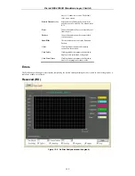
Страница 143: ...nicast Counts the total number of good packets that were received by a unicast address Multicast Counts the total number of good packets that were received by a multicast address Broadcast Counts the...

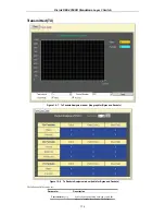
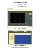
Страница 144: ...ackets Analysis window line graph for Bytes and Packets Figure 10 8 Tx Packets Analysis window table for Bytes and Packets The following fields can be set Parameter Description Time Interval 1s Select...

Страница 145: ...Hide Check whether or not to display Bytes and Packets Clear Clicking this button clears all statistics counters on this window View Table Clicking this button instructs the Switch to display a table...

Страница 146: ...llision fragments a normal network occurrence OverSize Counts packets received that were longer than 1518 octets or if a VLAN frame_1522 octets and less than the MAX_PKT_LEN Internally MAX_PKT_LEN is...

Страница 147: ...a line graph View Line Chart Clicking this button instructs the Switch to display a line graph rather than a table Transmitted TX Figure 10 11 Tx Error Analysis window line graph Figure 10 12 Tx Error...

Страница 148: ...at a collision is detected later than 512 bit times into the transmission of a packet Show Hide Check whether or not to display ExDefer LateColl ExColl SingColl and Coll errors Clear Clicking this but...

Страница 149: ...ding framing bits but including FCS octets 128 255 The total number of packets including bad packets received that were between 128 and 255 octets in length inclusive excluding framing bits but includ...

Страница 150: ...Address This allows the switch s dynamic MAC address forwarding table to be viewed When the switch learns an association between a MAC address and a port number it makes an entry into its forwarding...

Страница 151: ...or MAC address VID The VLAN ID of the VLAN the port is a member of MAC Address The MAC address entered into the address table Port The port that the MAC address above corresponds to Learned How the sw...

Страница 152: ...s that pass through the switch The number of IGMP reports that were snooped is displayed in the Reports field To view the IGMP Snooping table click IGMP Snooping Group on the Monitoring menu Figure 10...

Страница 153: ...splays information about the switch s current VLAN configuration Router Port This displays which of the switch s ports are currently configured as router ports A router port configured by a user using...

Страница 154: ...iew the Power Status of the Main Power Supply and the Redundant Power supply click on Power Status in the Monitoring menu Figure 10 21 Power Status table Port Access Control Authenticator State To vie...

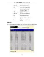
Страница 155: ...ess enter it into the field labeled IP Address at the top of the screen and click Find to begin your search Figure 10 23 IP Address Routing Table Routing Table The Routing Table window may be found in...

Страница 156: ...he corresponding icon revealing the following window This window holds the following information Parameter Description Interface Name Defines the interface name of the reporting multicast group Multic...

Страница 157: ...Adv Router ID is selected you must enter the IP address in the Advertisement Router ID field and then click Find If LSDB is selected you must select the type of link state RtrLink NetLink Summary ASS...

Страница 158: ...tual Neighbor This table can be found in the OSPF Monitoring folder by clicking on the OSPF Virtual Neighbor Table link This table displays a list of Virtual OSPF Neighbors of the Switch The user may...

Страница 159: ...warding multicast packets on outgoing interfaces Each entry in the DVMRP Routing Next Hop Table refers to the next hop of a specific source to a specific multicast group address This table is found in...

Страница 160: ...D Link DES 3350SR Standalone Layer 3 Switch 150 Figure 10 33 PIM Neighbor Table...

Страница 161: ...he Server IP Address field The TFTP server must be on the same IP subnet as the switch Enter the path and the filename to the firmware file on the TFTP server The TFTP server must be running TFTP serv...

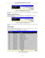
Страница 162: ...er and then click on the Upload log to TFTP Server link Figure 11 4 Upload log to TFTP Server window Enter the IP address of the TFTP server and the path and filename for the history log on the TFTP s...

Страница 163: ...ration changes permanently highlight Save Changes on the Maintenance menu The following screen will appear to verify that your new settings have been saved to NV RAM Figure 11 7 Save Configuration win...

Страница 164: ...ot window Reset Figure 11 9 Reset window Reset System Figure 11 10 Reset System window Reset Config Figure 11 11 Reset Config window Logout Figure 11 12 Logout Web Setup window Click Apply if you want...

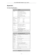
Страница 165: ...P 100 m 2 pair UTP Cat 5 100 m EIA TIA 568 100 ohm STP 100 m IEC 793 2 1992 Type A1a 50 125um multimode Type A1b 62 5 125um multimode SC optical connector Number of Ports 48x 10 100 Mbps NWay ports 2...

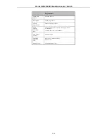
Страница 166: ...tering Address Table 8K MAC address per device Packet Filtering Forwarding Rate Full wire speed for all connections 148 800 pps per port for 100Mbps 1 488 000 pps per port for 1000Mbps MAC Address Lea...

Страница 167: ...ing are enabled At this point packets are forwarded by the port Blocking State A port in the blocking state does not forward packets When the switch is booted a BPDU is sent to each port in the switch...

Страница 168: ...ched Discards packets sent from another port on the switch for forwarding Does not add addresses to its forwarding database Receives BPDUs and directs them to the CPU Processes BPDUs received from the...

Страница 169: ...rd delay timer expires A port in the forwarding state does the following Forwards packets received from the network segment to which it is attached Forwards packets sent from another port on the switc...

Страница 170: ...disabled port does the following Discards packets received from the network segment to which it is attached Discards packets sent from another port on the switch for forwarding Does not add addresses...

Страница 171: ...ge of BPDUs between B and C B had a better BPDU than C B continues sending BPDUs advertising its superiority over the other bridges on this LAN Should C fail to receive these BPDUs for longer than the...

Страница 172: ...m with a ports transceiver Any failure that allows a link to remain up while providing one way communication is very dangerous for STP In this example port 2 on B can receive but not transmit packets...

Страница 173: ...ee each bridge increments the age field When this field is beyond the maximum age the packet is discarded For large diameter networks STP convergence can be very slow Identifying a Data Loop Broadcast...

Страница 174: ...uct In a domestic environment this product may cause radio interference in which case the user may be required to take adequate measures Warnung Dies ist ein Produkt der Klasse A Im Wohnbereich kann d...

Страница 175: ...nen l ngeren Zeitraum nicht benutzt sollten Sie es vom Stromnetz trennen Somit wird im Falle einer berspannung eine Besch digung vermieden 13 Durch die L ftungs ffnungen d rfen niemals Gegenst nde ode...

Страница 176: ...hase invoice must be provided If Purchaser s circumstances require special handling of warranty correction then at the time of requesting RMA number Purchaser may also propose special procedure as may...

Страница 177: ...pport at 1 877 453 5465 who will attempt to assist the customer in resolving any suspected defects with the product If the product is considered defective the customer must obtain a Return Material Au...

Страница 178: ...ts are designed to provide reasonable protection against harmful interference in a commercial installation This equipment generates uses and can radiate radio frequency energy and if not installed and...

Страница 179: ...egistration Register online your D Link product at http support dlink com register Product registration is entirely voluntary and failure to complete or return this form will not diminish your warrant...

Страница 180: ...accordance with the user manual and other documentation provided to the purchaser at the time of purchase or as amended from time to time D LINK does not warrant that the products will operate uninte...

Страница 181: ...4th Floor Merit House Edgware Road Colindale London NW9 5 AB United Kingdom Telephone 44 020 8731 5555 Facsimile 44 020 8731 5511 www dlink co uk...

Страница 182: ...rhafter Bedienung d Versagen von Produkten oder Diensten die nicht von D LINK stammen oder nicht Gegenstand einer zum ma geblichen Zeitpunkt g ltigen Garantie oder Wartungsvereinbarung sind e Fehlgebr...

Страница 183: ...lisation du produit non conforme ses sp cifications ou aux interfaces requises c d une mauvaise manipulation d d une panne de biens ou de services acquis aupr s d une soci t tierce non D LINK ou qui n...

Страница 184: ...requisitos de la interfaz en el funcionamiento del producto c manejo incorrecto d errores en art culos o servicios ajenos a D LINK o no sujetos a una garant a o un contrato de mantenimiento vigentes...

Страница 185: ...equisiti di connessione c movimentazione impropria d guasto di prodotti o servizi non forniti da D LINK o non soggetti a una garanzia successiva di D LINK o a un accordo di manutenzione e impiego o co...

Страница 186: ...Avenue North Ryde NSW 2113 Australia TEL 61 2 8899 1800 FAX 61 2 8899 1868 URL www dlink com au India D Link House Kurla Bandra Complex Road Off CST Road Santacruz East Mumbai 400098 India TEL 91 022...

Страница 187: ...______________________________ 4 What network operating system s does your organization use D Link LANsmart Novell NetWare NetWare Lite SCO Unix Xenix PC NFS 3Com 3 Open Banyan Vines DECnet Pathwork W...

Страница 188: ......
Отзывы: