RZN 4503-T
Montage und Installation
Mounting and Installation
99.823.87
1.1/1
1/08
D+H Mechatronic AG • Georg-Sasse-Str. 28-32 •
22949 Ammersbek • Tel.
40-605 65 239 • Fax
40-605 65 254 •
D-
+49
+49
www.dh-partner.com
1/2
©
2007
D+H
Mechatronic
AG,
Ammersbek
Alle
Maße
in
Millimeter
.
/
All
sizes
in
millimetre.
T
echnische
Änderungen
vorbehalten.
/
Rights
to
technical
modifications
reserved.
RAUCHABZUG
3.
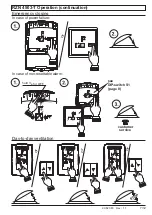
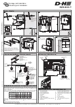
Akku anschliessen /
connect accumulator
1.
2.
Montage / Mounting
2
3
4
5
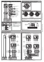
Leitungsverlegeplan (Muster) /
Wiring plan (example)
Leitungslängen und Querschnitte /
Line lengths and cross sections
Die angegebenen Aderzahlen und Querschnitte beziehen sich nur auf die benötigten Leitungen.
Bei Verwendung einer Leitung mit Schutzleiter (grün/gelb) wird dieser nicht mitgezählt und darf
nicht beschaltet werden. /
Number of wires and cross-sections indicated refer to required lines only. In case of using a line
with earthed conductor (green/ yellow), this one will not be counted in and must not be wired.
Gesamtstrom /
total current
0,5
1
1,5
2
2,5
3
A
3x 1,5 m m ²
240 120
80
60
48
40
m
3x 2,5 m m ²
400 200 130 100
80
65
m
*5x 2,5 m m ²
800 400 260 200 160 130
m
1x mind. /
12V / 3,2 Ah (Typ /
8)
1x at least
type
230V 50Hz
nicht abschaltbar /
not possible to
switch off
Brandmelder 24VDC
(z.B. FO 1362 oder FT 1262) /
Fire detector 24VDC
(e.g. FO 1362 or FT 1262)
Lüftungstaster 24VDC
(z.B. LT 43) ca. 1,2 m über OKFF
(bei UP bauseits 55mm UP - Dose) /
Vent button 24VDC
(e.g. LT 43) circa 1,2 m above upper
edge firm flooring (at flush type
at side 55mm flush socket)
JY (St) Y
2x2x0,6
zu weiteren /
to further ones
JY (St) Y
2x2x0,6
siehe Kabelverlegetabelle /
Hauptbedienstelle
Rauchabzugstaster /
Main control
smoke vent button
(RT43-H/N)
Nebenbedienstelle
Rauchabzugstaster /
Secondary control
smoke vent button
(RT43-H/N)
Kontakt Fremdansteuerung
z.B. Brandmeldezentrale /
Contact external control
e.g. fire alarm system
JY (St) Y
4x2x0,6
JY (St) Y
4x2x0,6
JY (St) Y
2x2x0,6
Zentrale RZN
Aufputz
(230VAC / 24VDC)
in der Nähe der RWA-Klappe. /
Control panel RZN
surface type
(230VAC/ 24VDC) in proximity of
smoke vent flap.
Antrieb(e) 24VDC
an Rauchabzugsklappe(n)
(Leitung in einer UP-Verteilerdose
enden lassen). /
Drive(s) 24VDC
at smoke vent flap(s)
(Lines must end in flush mounted
distribution box.)
1
2
3
4
5
6
7
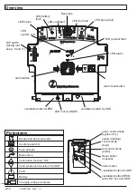
Platinenansicht /
Motherboard view
Sicherung ANTRIEBE /
F 2.5 A
fuse DRIVES
Schutzkappe* /
covering cap*
Netzanschluss /
power supply
1
2
3
4
5
6
7
Wind- Regenmelder 24VDC
(z.B. WRG 82) /
Wind- rain transmitter 24VDC
(e.g. WRG 82)
JY (St) Y
2x2x0,6
1
3x
1.
2.
Vorher:
Stockschrauben in
Kreuz eindrehen! /
Before:
screw hanger bolt
into tool!
1,36m
ab
OKFF
/
from
top
of
floor
*
ufsetzen/
Schutzkappe a
*put on covering cap
3x
Hinweis: Schriftzug bitte aus beiliegendem
Sprachenbogen heraustrennen und einsetzen. /
Hint: Please detach name plate from enclosed
language sheet
.
and put in
Kabelausbruch /
cable breakout
Linie /
line
Netz /
mains
Gruppe /
group
110
183
203
6
Querschnitt /
(mm²)
cross section
einfache Kabellänge /
(m) x Gesamtstrom /
80
plain cable length
total current
=
*2 Adern je Antriebsleitung parallel schalten. /
*Connect in parallel 2 wires for each drive line
zu weiteren /
to further ones
see cable wiring table
*
*
Melderelais 1 /
signalling relay 1
Melderelais 2 /
signalling relay 2
-
+
A
K
S
M
Z
B
: notversorgtes Potential -
: notversorgtes Pot
nicht notversorgtes Pot
: Sammelalarm
: Kontrolle
: Sammelstörung
: Ansteuerung Haftmagnete
: Eingang,Zentralfunktion Schließen der Gruppe
: BMZ-Eingang
N-
N+
: nicht notversorgtes Potential -
:
Klemmenbelegung E-Platz / Clamp assignment E-Slot
-
+
N+
A
K
S
M
Z
B
: emergency-supplied electric potential -
: emergency-supplied electric pot
: electric pot, without emergency supply
:
:
ontrol
: general malfunction
: magnetic clamp
: input, central function, closing of group
: BMZ input
N-
: electric potential -, without emergency supply
general alarm
c
control


