JF-1A Conductivity Sensor
A440-009
Page 40 of 56
FEBRUARY 2009
Power input to the JF-1A is required in order for the instrument to operate
properly. If multiple output data sources from the JF-1A are to be used then the
sensor needs multiple power inputs. In all cases, it is very important that power
inputs are wired correctly to the JF-1A; harm can come to the sensor due to
improper power levels or connection of multiple grounds that may be at
different voltages.
Definition: Power isolation. Power is isolated when it is fully floating with
respect to ground and/or other power sources. I.E. if two isolated power
supplies are in use, you cannot measure the voltage of one with the return lead
of the voltage measuring device attached to the other.
All power sources used with the JF-1A should be isolated both from ground, but,
also from each other. Be cautious of common grounds (tie points) in PLC
analog input channels; consult your PLC user’s manual.
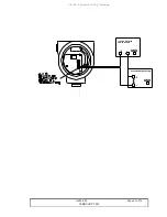
Example 1
JF-1A Conductivity Current Device Loop:
This is the standard configuration, a 24 VDC isolated power supply supplies loop
power and a 250 ohm sense resistor is used to sense the conductivity current in
the loop (convert the current to a voltage in the PLC). The JF-1A derives its
power for its operation from the loop current supply.
Note
: both the supply
and loop current detector are normally isolated from ground .

